 DIY GUY Chris
Supplies
Hardware Components:
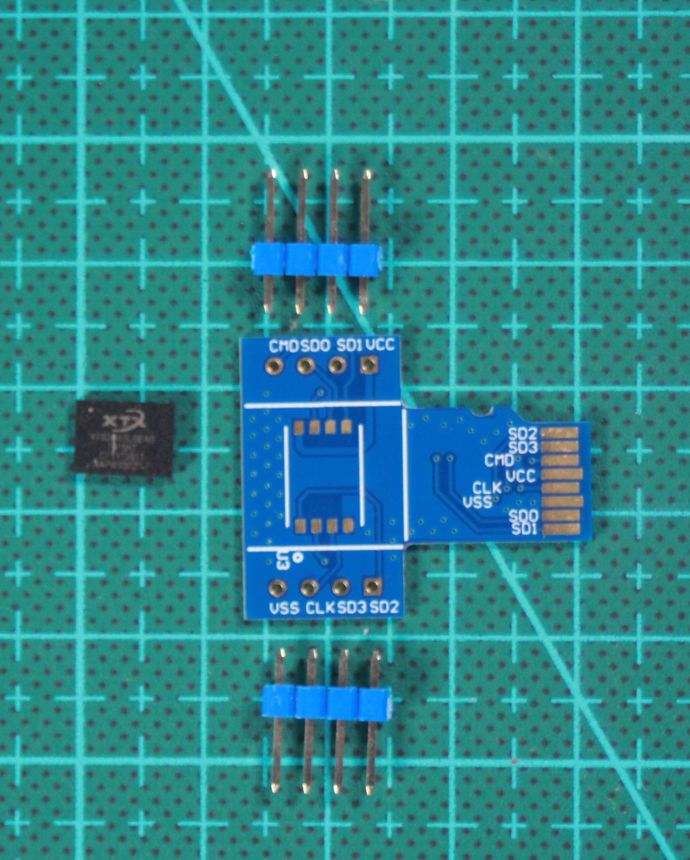
- XTX XTSD04GLGEAG SD card chip
- Arduino board (Uno, Nano, or compatible)
- Custom PCB (design files provided)
- 2.54mm SIL pin headers (2x5 pins)
- Solder paste (type 4 recommended)
- Soldering iron with fine tip
- Hotplate or reflow oven
- Breadboard and jumper wires
- SD card reader (for initial testing)
Software Tools:
- Arduino IDE (latest version)
- SdFat library by Bill Greiman
- Altium Develop (or your preferred PCB design tool)
- Serial terminal program (like PuTTY or Arduino Serial Monitor)
Manufacturing Services:
- JLCPCB or similar PCB fabrication service
- (Optional) 3D printer for enclosure
Schematic and PCB Design
Start by designing the breakout board in your preferred PCB design software. I used Altium Develop for this project.
Design Considerations:
- Create a schematic that duplicates the XTSD chip for top and bottom assembly
- Connect all chip pins to SIL connectors for easy breadboard compatibility
Follow standard SD card layout for the edge connection if you want reader compatibility

- Follow standard SD card layout for the edge connection if you want reader compatibility
- Set PCB thickness to 0.6mm - this is crucial for fitting into standard SD card readers.
- Use 0.2mm trace width for signal line
- Add clear pin labeling for easy wiring reference

Manufacturing Preparation:
- Generate Gerber files from your design
- Choose a solder mask color (I went with JLCPCB's signature blue)
- Select ENIG (Gold Nickel) surface finish for better solderability
- Verify all design rules before submission
Pro Tip: You can access my complete design files through the GitHub repository linked at the end of this guide.
Circuit Assembly
Once your PCBs arrive, it's time for assembly. The XTSD chip has a QFN package, which requires careful soldering.

Soldering the XTSD Chip:
- Apply solder paste to all chip pads using a stencil or careful manual application
- Use tweezers to precisely place the chip on the pads
- Heat the board using a hotplate or reflow oven until the solder melts and reflows
- Allow the board to cool naturally - don't force cool it!
Microscopic Inspection:
After soldering, use a microscope or magnifying glass to check for:
- Bridging between pins
- Proper solder fillets Chip alignment
Adding Connectors:
- Insert SIL pin headers into a breadboard
- Place the PCB on top, aligning the holes with the pins
- Solder each pin using a fine-tip soldering iron
- Use copper braid to clean up any excess solder
Safety Note: Work in a well-ventilated area and use ESD protection when handling the chip.
Wiring to Arduino
The XTSD chip uses standard SPI interface, making Arduino integration straightforward.
SPI Connection Diagram:

XTSD04GLGEAG → Arduino Pin
─────────────────────────
CS (Chip Select) → D10
MOSI (Master Out) → D11
MISO (Master In) → D12
SCK (Clock) → D13
VCC (Power) → 3.3V
GND (Ground) → GND
Breadboard Setup:
- Place the breakout board on your breadboard
- Connect power lines first (3.3V and GND)
- Connect the four SPI signals (CS, MOSI, MISO, SCK)
- Double-check all connections before powering on

Important: The chip requires 3.3V power! Do not connect it to 5V as this will damage the chip.
Final Test and Results
Upload the Code:
- Install the SdFat library via Arduino Library Manager
- Open the provided Arduino sketch
- Select your board and port
- Upload the code to your Arduino

Serial Interface Test:
- Open Serial Monitor at 9600 baud
- You should see the main menu with 8 options
Test each function:
- List files (should show any existing files)
- Create a new text file
- Write data to the file
- Read back the data
- Delete files (with confirmation)
- View SD card information
- Test each function: List files (should show any existing files) Create a new text file Write data to the file Read back the data Delete files (with confirmation) View SD card information
Cross-Platform Testing:
- Remove the board from Arduino
- Insert it into a computer's SD card reader
- Verify the computer recognizes...
 Dan Schnur
 vishal soni
 Sagar 001
 Corey Harding