 Stanislav Britanishskii
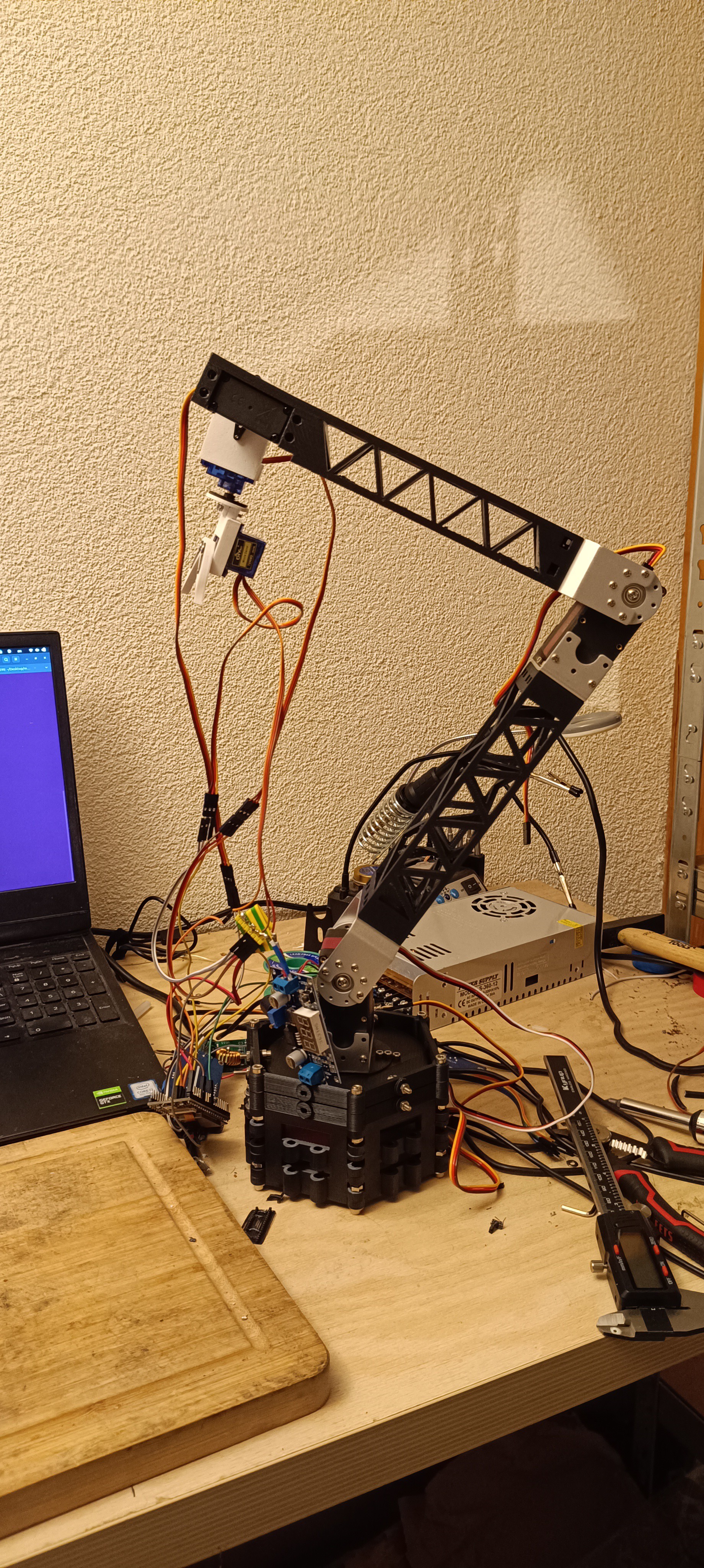
Since the last log quite a lot happened: I burned a power supply, ordered more parts, and mostly finished the arm mechanics.
For the upper and lower arm segments I borrowed the look from crane booms. The lattice structure with triangular cutouts turned out to be surprisingly light and stiff, and was very easy to model in FreeCAD – just a few sketches and patterned triangles. The photo shows the first full “skeleton” of the arm assembled and moving.
Cabling is still a disaster. I’m still using random jumper wires and too many soldered joints, which leads to frequent short circuits. That’s how I killed the previous power supply. The new one seems to survive better (probably has slightly less terrible protection), but these cheap units have plenty of Amazon reviews with pictures of actual flames, so I don’t fully trust it. I’ve ordered proper cables and connectors; they should arrive at the end of this week or the beginning of next.
For the rotating base I decided to use a 60 kg servo, same model as in the elbow. It’s weaker than the 150 kg servo in the shoulder, but it’s also much cheaper. To reduce the load on the base servo I designed a circular platform the arm mounts to, and that ring is held between bearings attached to the base body. The servo just has to drive rotation; the bearings carry most of the weight. It’s working, but the whole base is still too unstable, so next step is a bottom part that clamps to the table with some printable clamp design I’ll probably steal from the internet.
Overall, the results so far are better than I expected. I was mentally prepared for a lot more setbacks at this stage. There is still a long way to go, but seeing the full-length arm move on the bench is very motivating.
Discussions
Become a Hackaday.io Member
Create an account to leave a comment. Already have an account? Log In.