First of all you have to open the back cover of the remote control and as next step the additional cover with the nameplate. Now you have the back side of the PCB in front of you with all the test-points. You can now also remove the PCB, but that's not needed! All you need are the test-points which directly connect to the buttons. The following picture show you the relevant test points:
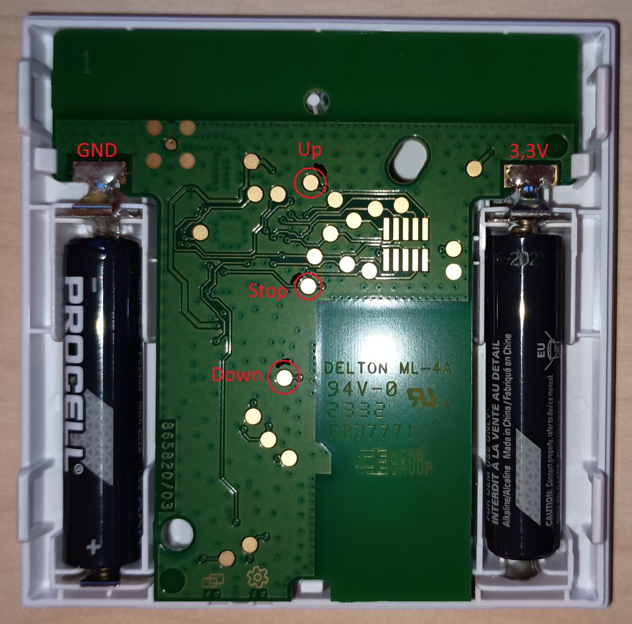 The buttons are connected via pull-up to the supply (around 3V) and are pushed to GND by the buttons.
Hint: In the internet there are various projects which directly connect the test points to a microcontroller (e.g. ESP8266) GPIO port. I wouldn't recommend this solution as you now will short the GPIO port to GND if you push the button (exception: You can configure the GPIO port to open-collector like some STM32 can do). If you nevertheless want to use this solution: Check that you GPIOs are working with 3.3V.