 Arnov Sharma
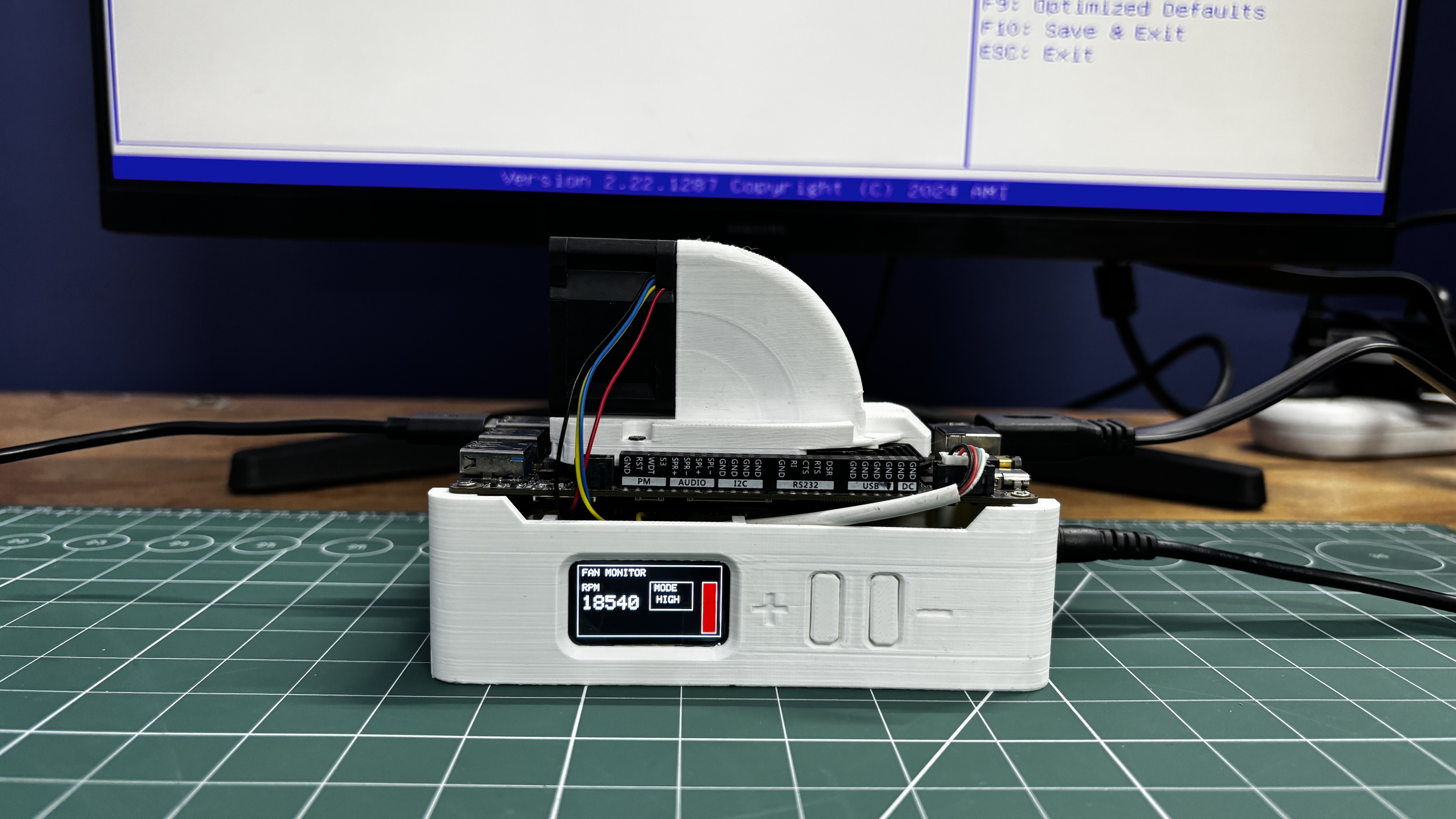
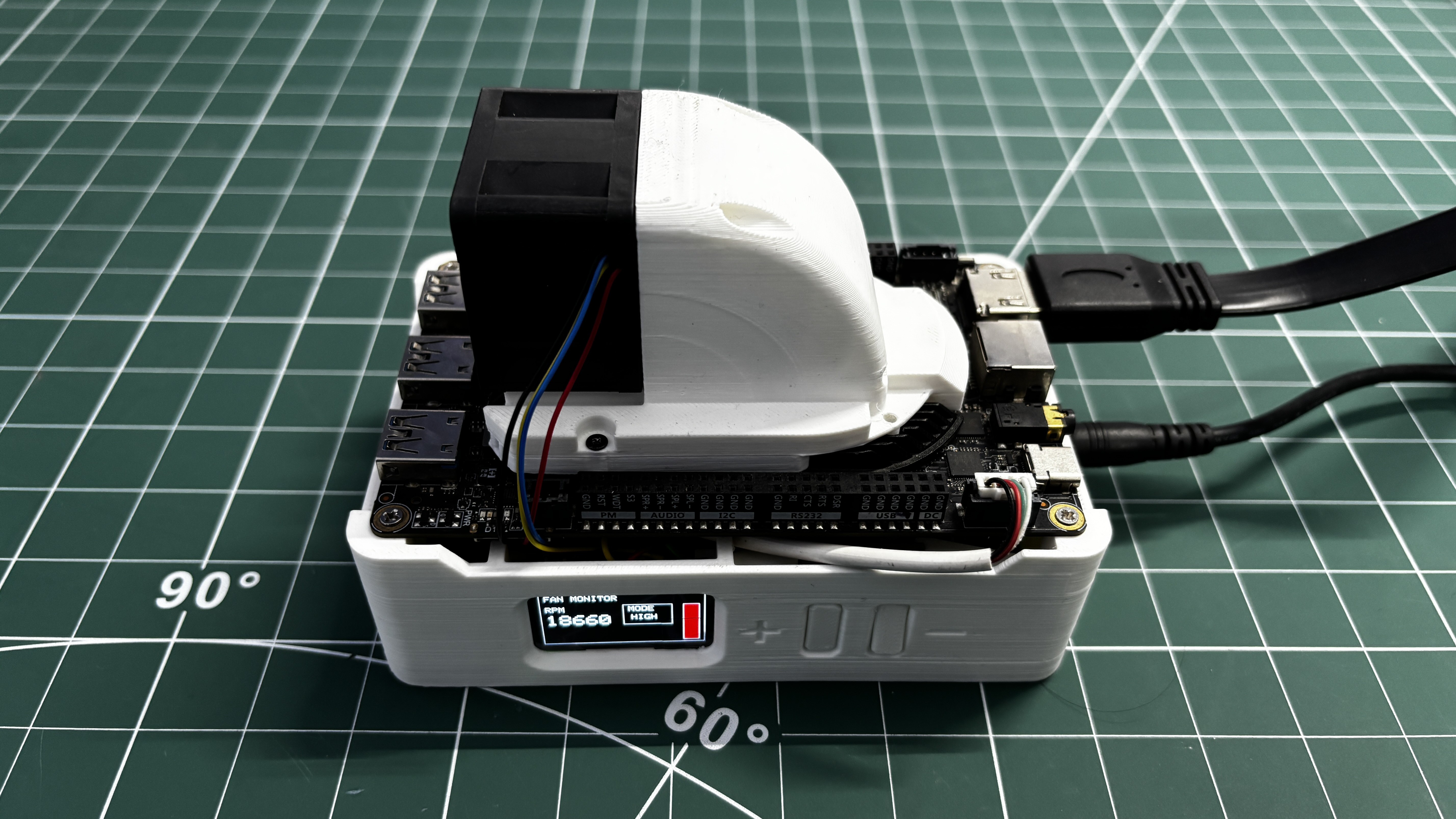
The cooling module is integrated into a portable stand that holds the LattePanda Delta securely and includes an onboard display for showing fan RPM and operating mode, along with physical buttons for controlling fan speed.
This article covers the complete build process, from the mechanical design and airflow considerations to the electronics, fan control system, and final assembly.
MATERIAL REQUIRED
These were the materials used in this build:
- Lattepanda MU with full evaluation board
- Custom Switch PCB (provided by PCBWAY)
- PF40281B1-000U-S99 Server BLDC FAN 12V
- ESP32 S3 1.47 Inch Waveshare Display
- DFROBOT Rainbow Link
- 3D-printed parts
- DC-DC Buck Converter
COOLING FAN ISSUE ON LATTEPANDA 3 DELTA
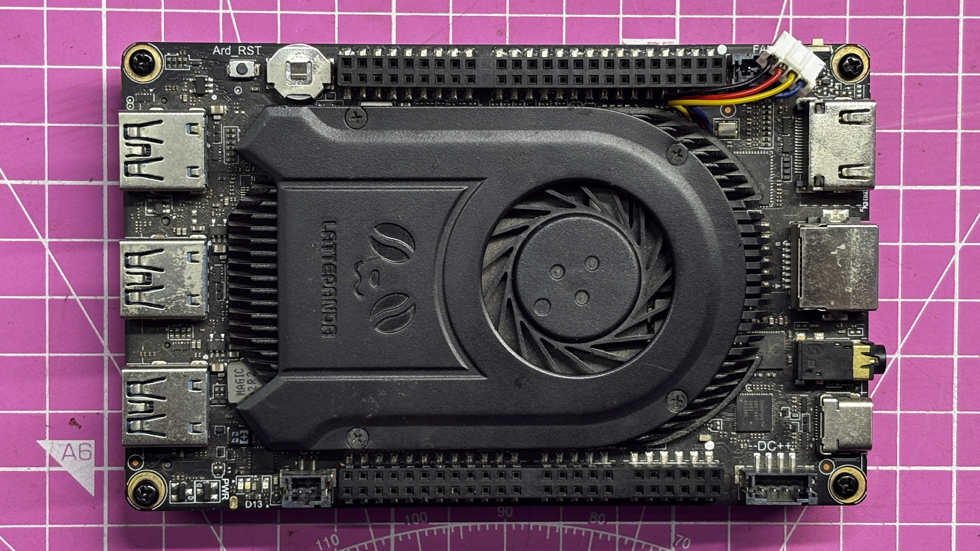
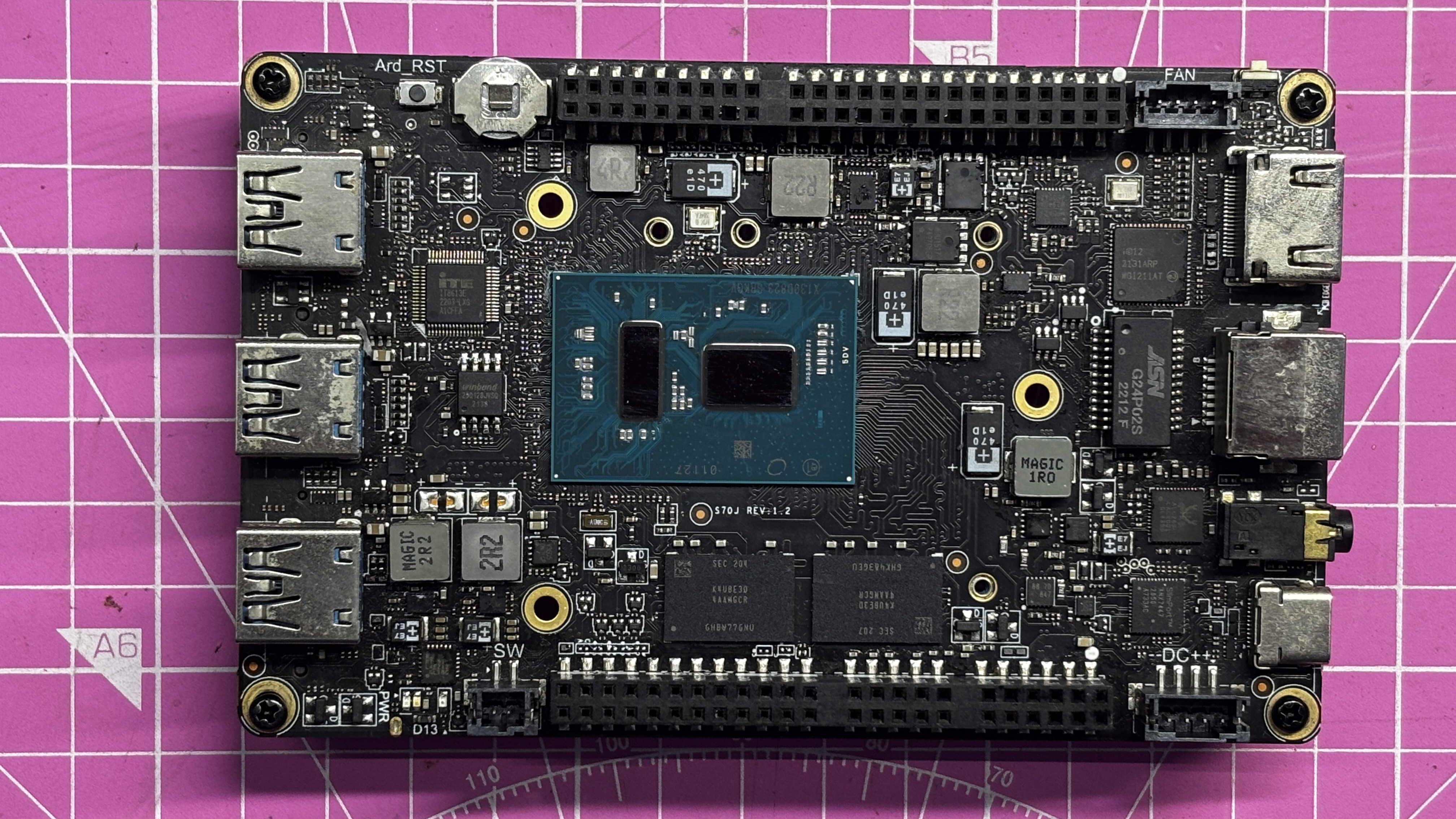
This is my very first LattePanda, which I’ve been using regularly since 2022. A couple of weeks ago, its onboard cooling fan completely stopped working. I’ve used this LattePanda in several previous projects, and apart from the cooling system, the processor and all other electronics were still functioning perfectly—the only failure was the cooling section itself.
Rather than waiting for a replacement cooling unit, I decided to investigate the issue and design my own solution.
As a first step, I tested the original BLDC fan by supplying it with 12 V, ground, and a PWM signal on the control wire, but the fan did not respond. To rule out a faulty fan, I connected a different 12 V BLDC fan with a JST connector to the onboard fan header, but that fan also failed to operate.
From this, I concluded that something had gone wrong with the onboard fan-driving circuitry itself—likely due to damage or a short—rendering the original cooling control system unusable.
At that point, the only practical solution was to build an externally powered and externally controlled cooling system, which ultimately led to this project.
FAN TEARDOWN
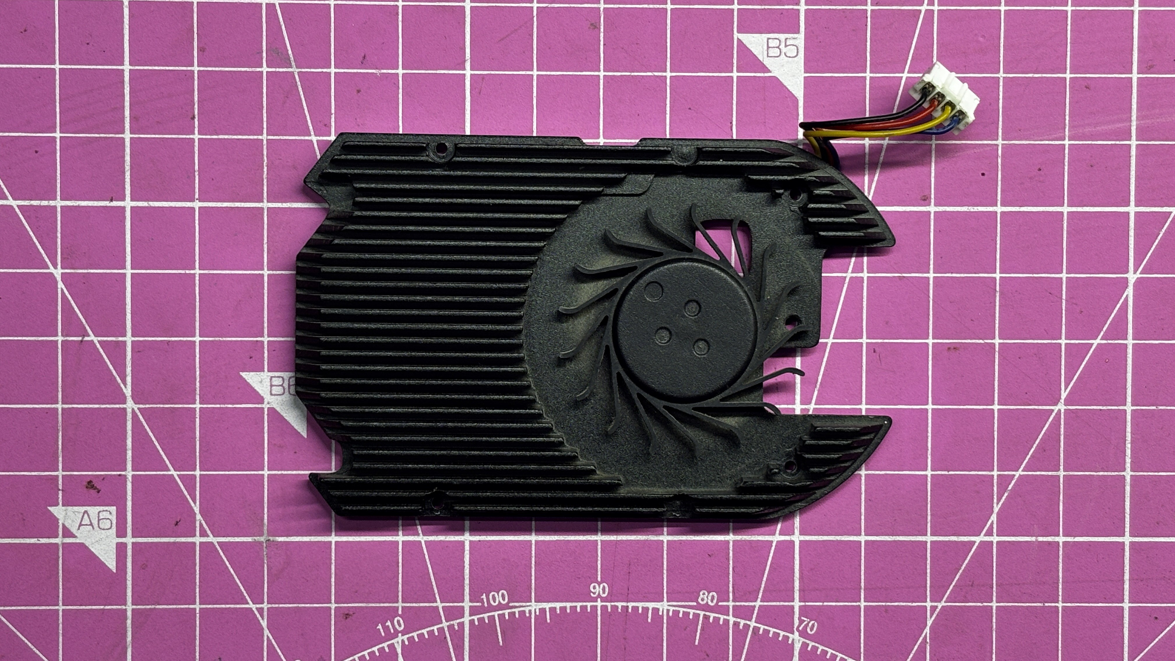
We began the project by tearing down the original cooling fan assembly. The process was straightforward at first but became more tedious as we progressed. The teardown started by unplugging the fan connector from the board. Next, we removed the four M2 screws securing the top plastic cover. After that, three additional M2 screws were removed from the underside, which released the heatsink from its mounting position. This allowed the entire heatsink assembly to be removed from the board.
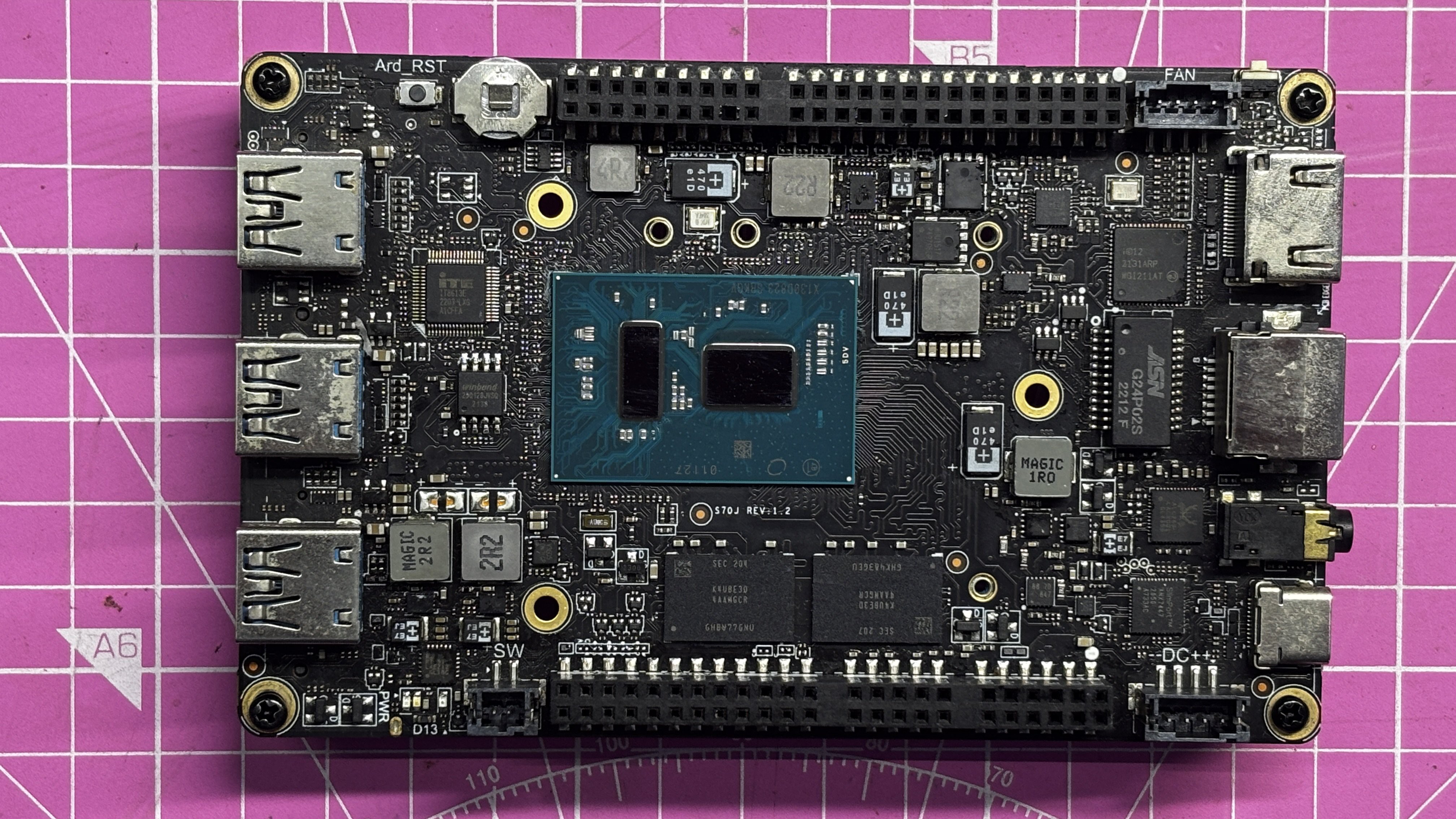
Once the heatsink was removed, both the heatsink base and the processor surface were cleaned using isopropyl alcohol to remove the old thermal paste. Care was taken not to apply excessive pressure while cleaning the processor, as doing so could dislodge nearby SMD components and permanently damage the board.
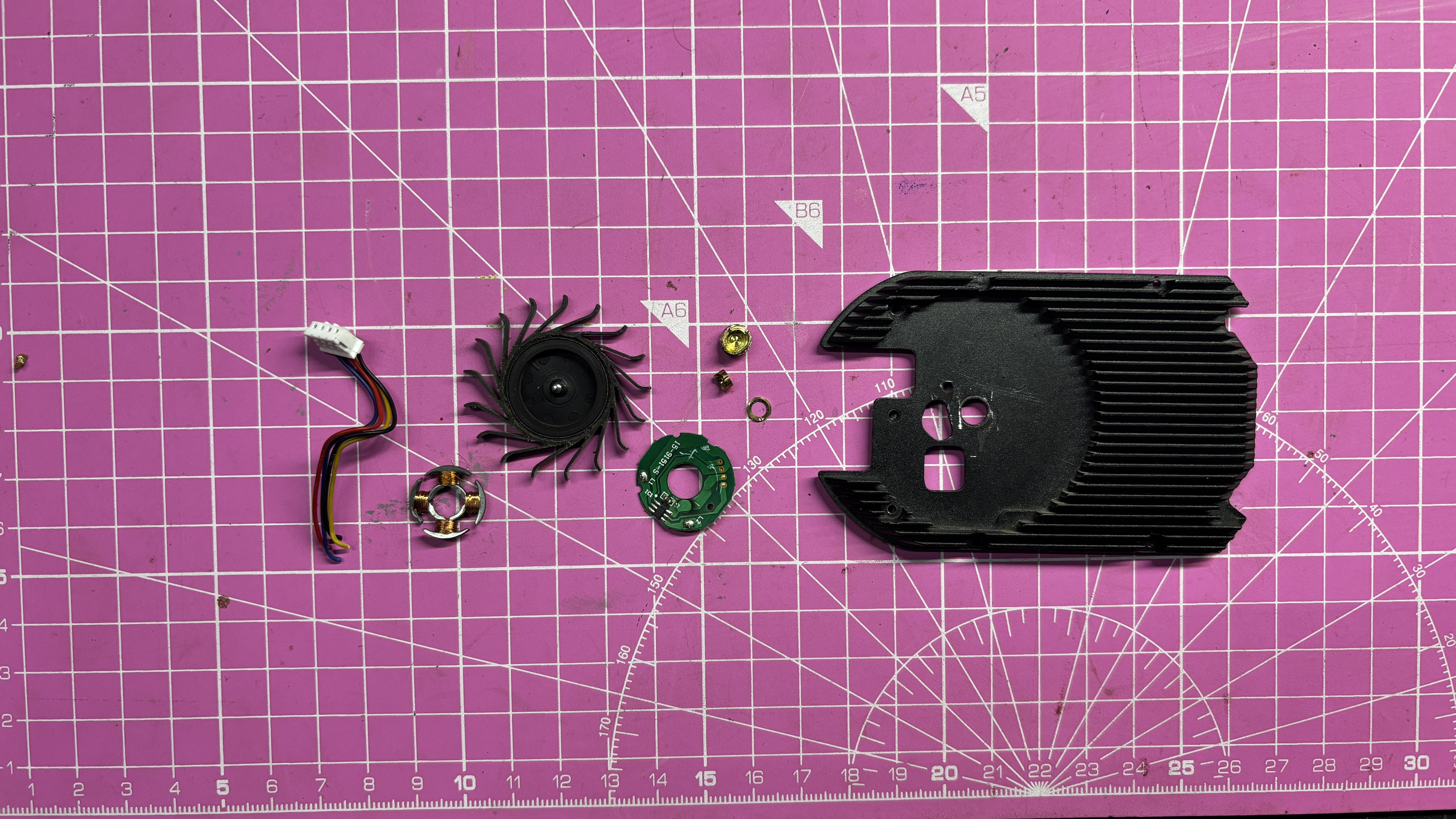
With the heatsink cleaned, we proceeded to remove the onboard fan from it. The fan was disassembled by first removing the rotor, followed by the stator assembly. The stator was connected to a small driver PCB, which was also removed completely, along with the brass bushing mounted in the heatsink.
After stripping away all fan-related components, we were left with a bare heatsink. This heatsink would later be reused in combination with a custom-designed airflow duct and an external server fan as part of the new cooling solution.
EXTERNAL SERVER FAN SETUP
For the cooling system, we reused an older Sunon PF40281B1-000U-S99 tubeaxial DC brushless server fan. This fan operates at 12 V, has a power rating of 6.7 W (relatively low power for a server-class fan), and can reach a maximum speed of 20,000 RPM, with an airflow rating of 24.9 CFM.
For comparison, a typical 40 mm × 40 mm PC fan delivers around 5.4 CFM, which is significantly lower. This large difference in airflow explains why server-grade fans are far more effective at cooling dense heat sinks. While this fan is noticeably louder than a regular PC fan, the substantial increase in airflow makes it a worthwhile trade-off for this application.
https://www.digikey.in/en/products/detail/sunon-fans/PF40281B1-000U-S99/4840557
The BLDC fan uses a standard four-wire interface:
- Red—VCC (12 V)
- Black—Ground
- Yellow—Tachometer output for RPM feedback
- Blue – PWM input for speed control
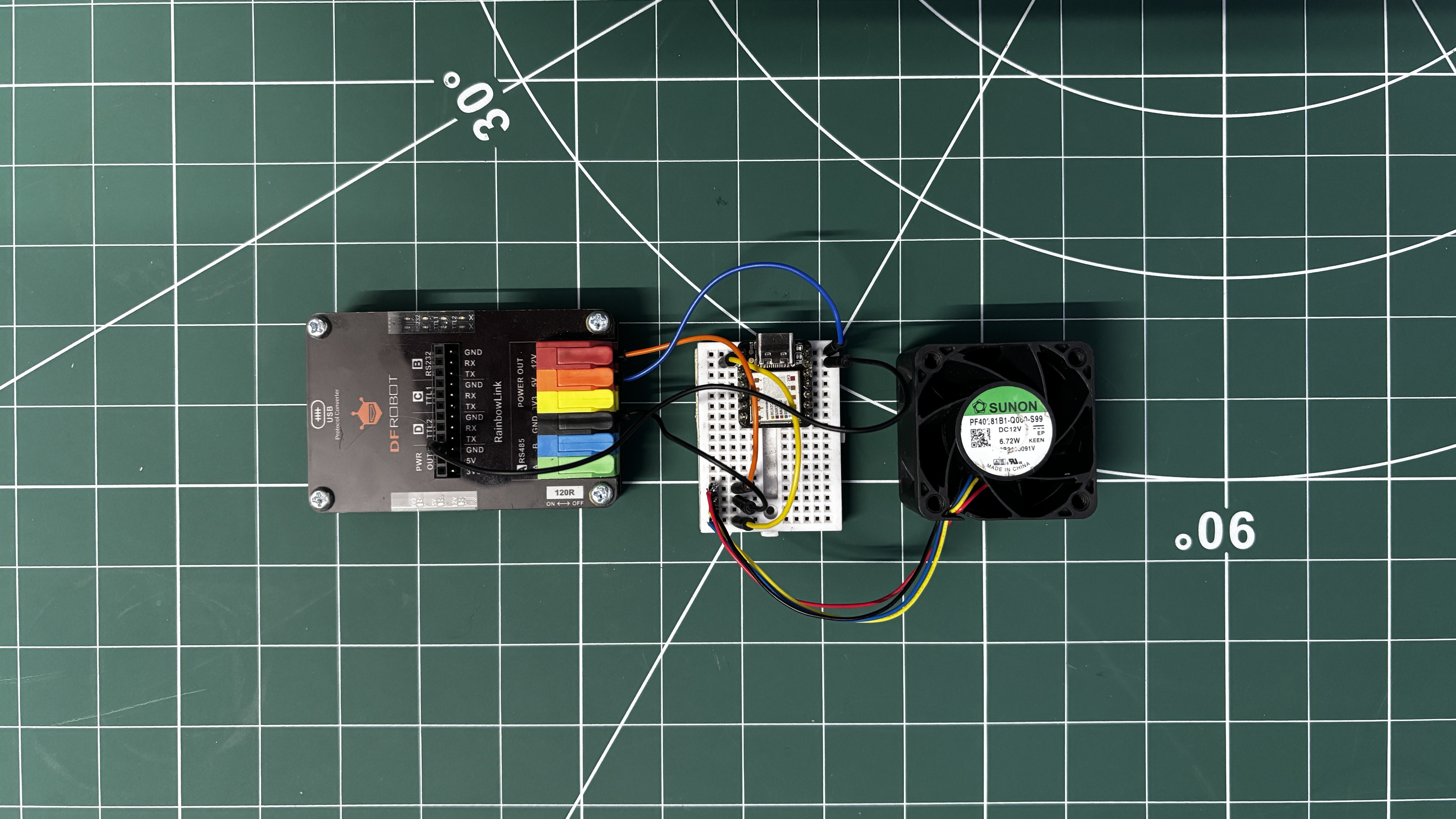
For fan control and testing, we used a Seeed Studio XIAO SAMD21 (XIAO M0), although any microcontroller capable of generating a PWM signal and reading a tachometer output can be used. The fan’s ground is connected to the microcontroller ground, the PWM control wire (blue) is connected to GPIO 0, and the tachometer output (yellow wire) is connected to GPIO 1.
To power the fan, we used DFRobot Rainbow Link, a protocol converter board that accepts a USB-C power adapter and provides multiple regulated outputs, including 12 V, 5 V, and 3.3 V. In this setup, the fan’s 12 V supply (red wire) is connected directly to the 12 V output of the Rainbow Link.
The ground of the XIAO is tied to the ground of the Rainbow Link to establish a common reference. The 5 V output from the Rainbow Link is also connected to the 5 V pin of the XIAO to power the microcontroller, completing the circuit.
We next uploaded the below test code in XIAO and opened the serial monitor.
const int fanPWM  = 0;   // Blue wire
const int fanTach = 1;   // Yellow wire (interrupt)
volatile unsigned int pulseCount = 0;
unsigned long lastRPMTime   = 0;
unsigned long lastModeTime  = 0;
int mode = 0;   // 0=LOW, 1=MED, 2=HIGH, 3=OFF
// Interrupt: count tach pulses
void countPulse() {
pulseCount++;
}
void setup() {
pinMode(fanPWM, OUTPUT);
pinMode(fanTach, INPUT_PULLUP);
attachInterrupt(digitalPinToInterrupt(fanTach), countPulse, FALLING);
analogWrite(fanPWM, 0);
Serial.begin(9600);
}
void loop() {
unsigned long now = millis();
/* -------- RPM CALCULATION (EVERY 1s) -------- */
if (now - lastRPMTime >= 1000) {
noInterrupts();
unsigned int pulses = pulseCount;
pulseCount = 0;
interrupts();
// 2 pulses per revolution
int rpm = (pulses / 2) * 60;
Serial.print("Mode: ");
Serial.print(mode);
Serial.print(" | RPM: ");
Serial.println(rpm);
lastRPMTime = now;
}
/* -------- FAN MODE CHANGE (EVERY 5s) -------- */
if (now - lastModeTime >= 5000) {
mode = (mode + 1) % 4;
switch (mode) {
case 0: analogWrite(fanPWM, 80);  break;   // LOW
case 1: analogWrite(fanPWM, 150); break;   // MED
case 2: analogWrite(fanPWM, 255); break;   // HIGH
case 3: analogWrite(fanPWM, 0);   break;   // OFF
}
lastModeTime = now;
}
}
The fan’s PWM control wire is connected to GPIO0, and the XIAO cycles the fan between low, medium, high, and off states every 5 seconds. At the same time, the fan speed is measured using the tachometer output, and the calculated RPM is displayed on the serial monitor.
ESP32 S3 DEV BOARD
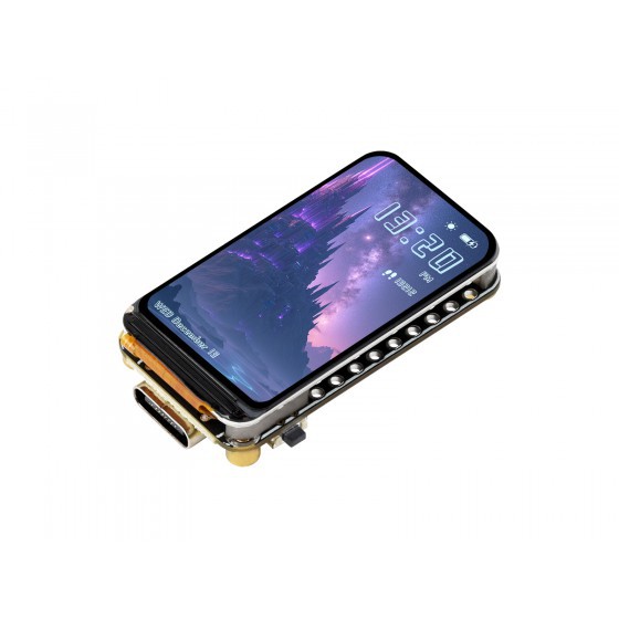
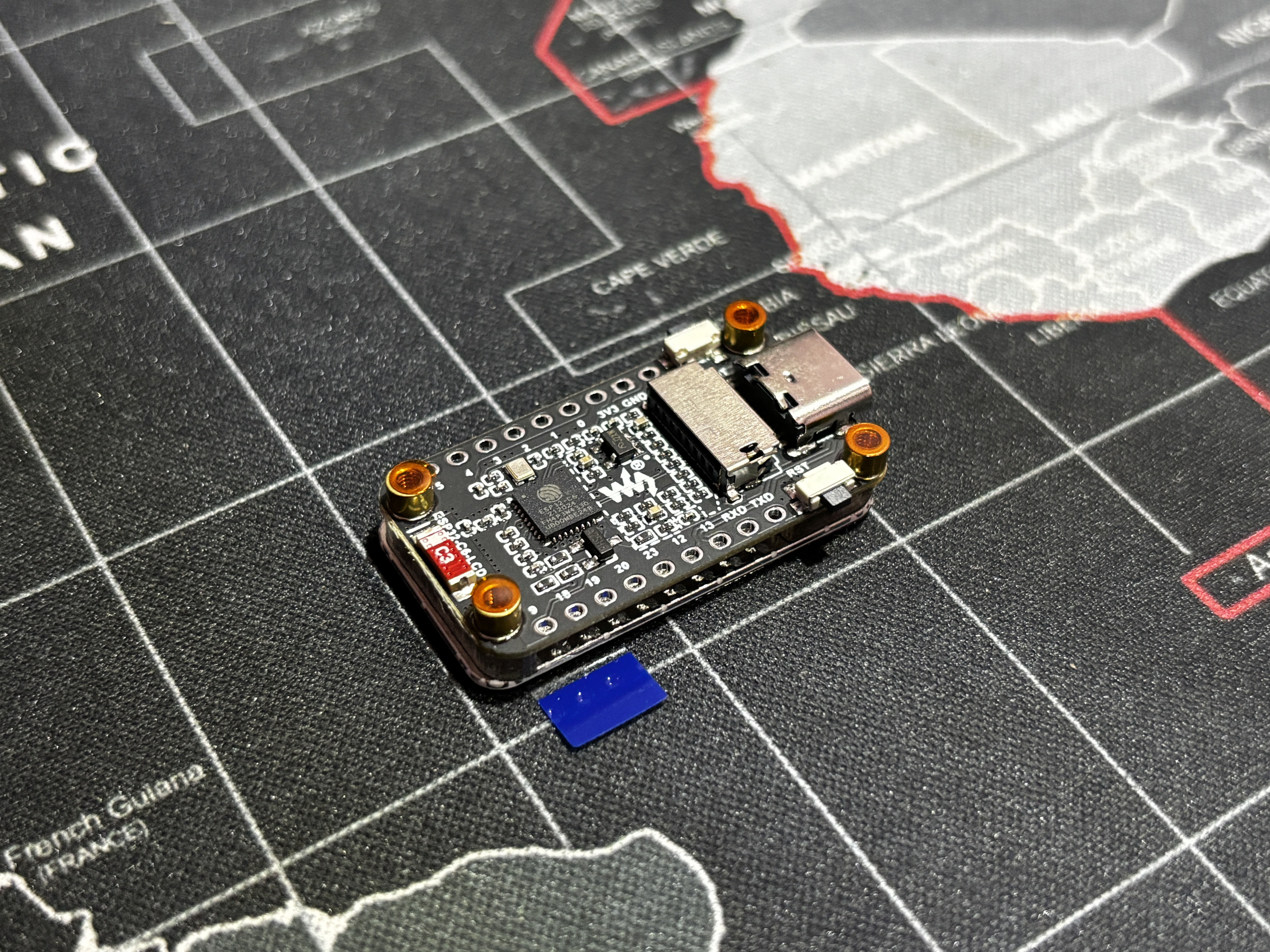
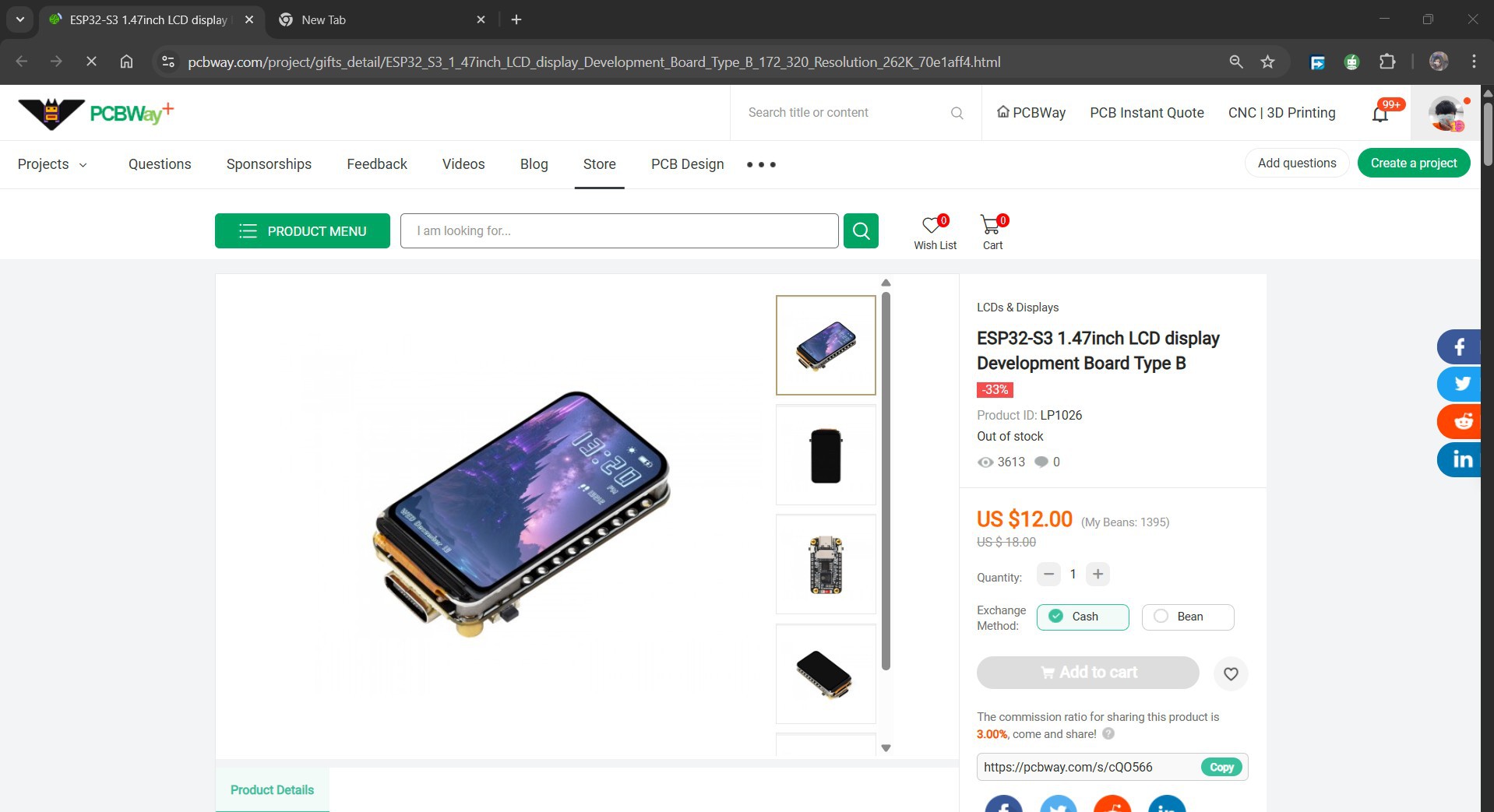
For the main microcontroller, we are using the ESP32-S3 LCD 1.47" Display Board by Waveshare. The name might be long, but the board itself is surprisingly compact, and it packs a lot of power into a small footprint. At its core, the board is powered by an ESP32-S3 microcontroller, featuring a dual-core 32-bit Xtensa LX7 processor running at up to 240 MHz, along with built-in Wi-Fi (802.11 b/g/n) and Bluetooth 5 (LE) support. It comes with 8 MB of Flash and PSRAM, making it well suited for applications that require graphics, real-time data processing, and responsive user interfaces. The board integrates a 1.47" SPI-based ST7789 LCD display with a resolution of 172 × 320 pixels and support for 262K colors. Despite its small size, the display is crisp and vibrant, making it ideal for compact UI elements such as fan RPM readouts, mode indicators, and status screens. For interaction and expansion, the board includes an onboard RGB LED for visual feedback, a TF (microSD) card slot, and a GPIO header that allows additional peripherals to be connected directly. The ST7789 display works reliably with graphics libraries such as Adafruit GFX and LVGL, making UI development straightforward. You can check out more about this display from its wiki page. https://www.waveshare.com/wiki/ESP32-C6-LCD-1.47 Also, for sourcing this display, we got it from PCBWAY's gift shop. https://pcbway.com/s/cQO566
SWITCH PCB
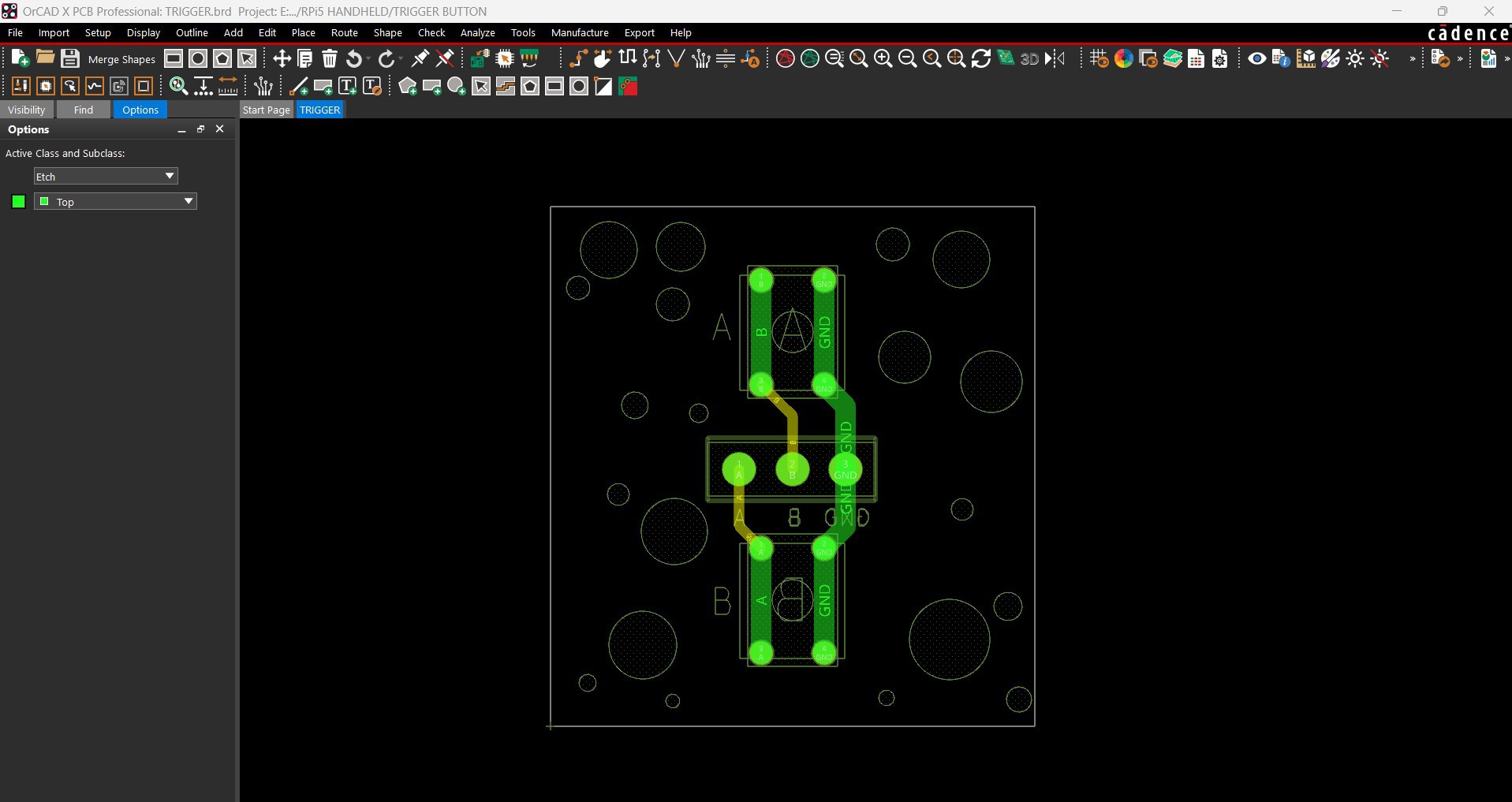
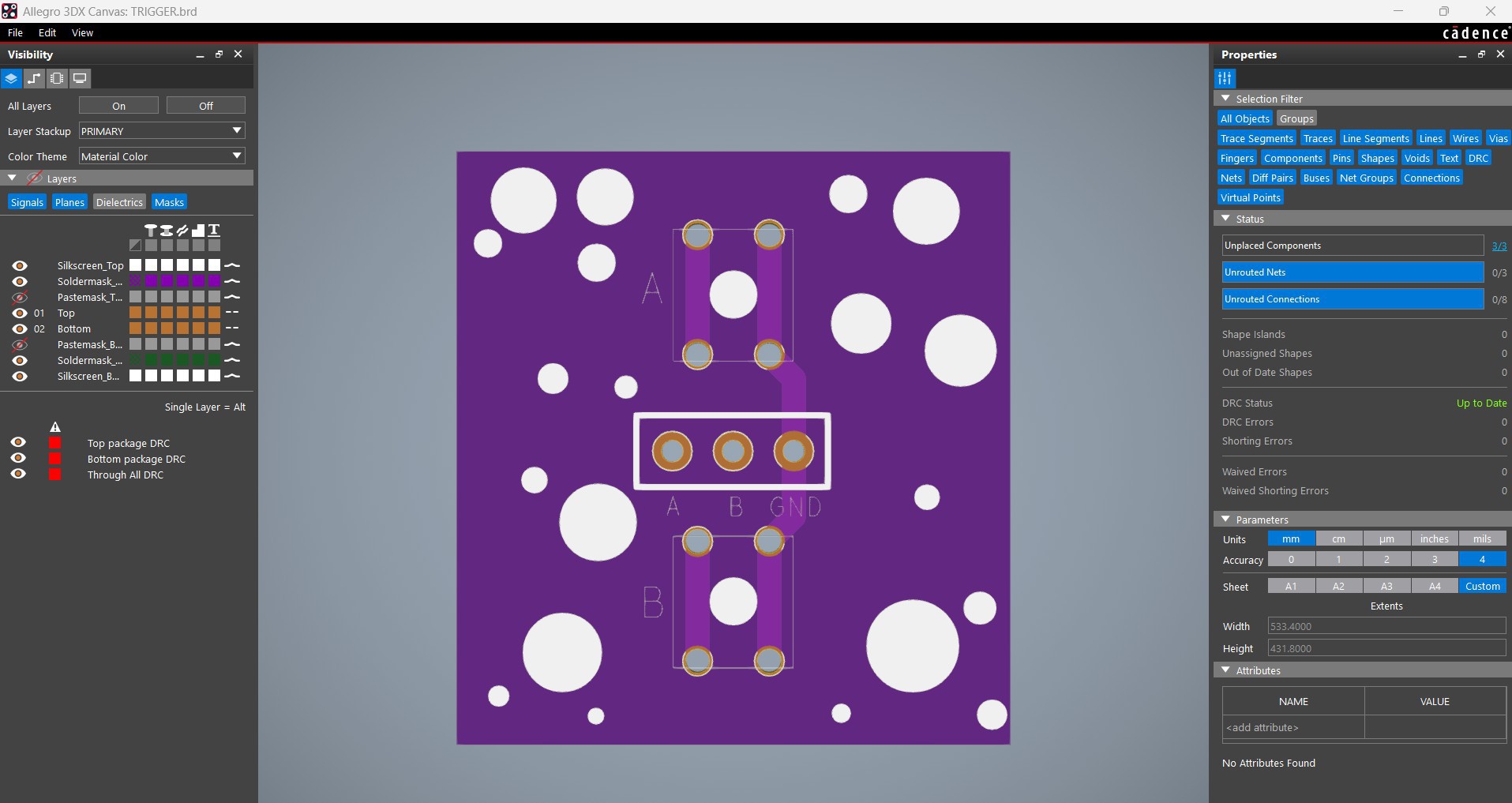
For this project, we reused one of our previously designed switch PCBs. The board consists of two 4×4 tactile push buttons wired in a pull-down configuration. The ground pins of both switches are connected together, and each button pulls its respective signal line low when pressed, allowing the microcontroller to reliably detect button presses. After finalizing the schematic, we designed the PCB and added a few custom elements to the silkscreen layer to improve its overall aesthetics and make the board easier to identify during assembly. Once the design was complete, the Gerber files were exported and shared with a PCB manufacturer for fabrication.
PCBWAY SERVICE
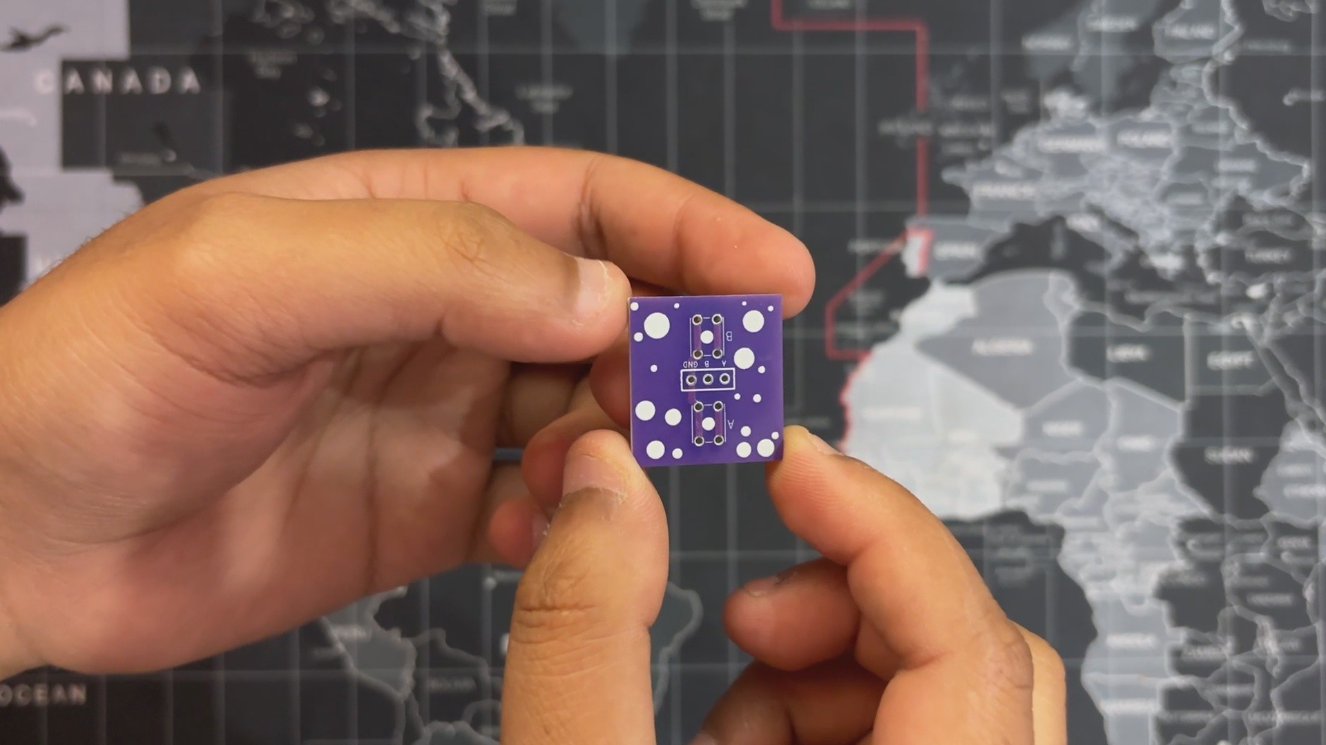
After finalizing the PCB design, we exported the Gerber files and uploaded them to the quote page on PCBWay.
For this project, we chose a purple solder mask with white silkscreen. The PCBs were delivered within a week, and the quality was excellent, as always. While I usually stick to white or standard black solder masks for most of my builds, this time I decided to try PCBWay’s purple finish. This was partly inspired by their Christmas sale campaign, during which matte black, purple, and pink solder mask options were available for a limited time. Over the past ten years, PCBWay has distinguished themselves by providing outstanding PCB manufacturing and assembly services, becoming a trusted partner for countless engineers and designers worldwide. Also, PCBWay is organizing the PCBWay 8th Project Design Contest, a global event that invites makers, engineers, and innovators to showcase their most creative builds. With categories in Electronics, Mechanical, and AIoT, it’s a great opportunity to share your work, connect with the community, and compete for exciting prizes. You guys can check out PCBWAY if you want great PCB service at an affordable rate.