Ai-Thinker
I had an AI-M61-32S development board on hand. The board integrates LEDs, serial interfaces, Wi-Fi, and Bluetooth. With this board available, what was still missing for an automatic jump rope counter were: a display, buttons, a buzzer, a charging/discharging circuit, and a counting sensor.
For the display, I planned to use a 0.96-inch OLED, which is sufficient to show jump rope data and remains clearly visible at all times. Two tactile buttons are used: one for setting the time, and the other for starting or canceling the counting process. Charging is handled using a GX4056 charging IC and a low-dropout LDO regulator from existing stock, making the circuit simple to design. For counting, an ITR9606 infrared sensor and LM393 comparator are used to implement an infrared break-beam counting method.
After finalizing the hardware, I began a simple circuit design. The overall design follows a modular approach to make assembly and disassembly easier. The PCB mainly includes the counting circuit, charging circuit, buttons, buzzer, and pin header connectors for the development board and the OLED. Due to the use of pin headers and sockets, the overall thickness of the device is relatively large.
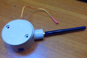
For the mechanical design, the main challenge was fixing the rotating shaft of the jump rope. Since I don’t know how to use 3D modeling software, my approach was to purchase ready-made parts from Taobao and assemble them manually. After searching, I ended up with a rather unusual combination: a 5 mm diamond-shaped bearing block with mounting holes and PCB solder terminals, which together allowed the shaft and optical encoder disk to be fixed directly onto the PCB.
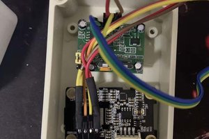
After receiving the PCB, I first soldered the small components and tested the battery charging circuit and OLED display.
After testing, I mounted the board onto a bracket and measured the dimensions to determine the enclosure size.
Fully assembled without enclosure
For the enclosure, I directly used the 3D enclosure design feature in EasyEDA to create a simple case. Although I carefully measured many dimensions before designing the enclosure, after printing it I found that the power switch was too long, preventing the PCB from fitting inside. In the end, I drilled holes in the frame and bent the switch slightly, which allowed the board to fit.
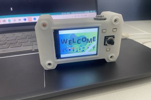
Assembled with enclosure:
Then I attached a jump rope and assembled everything together.
Software Design
For the software, I referenced many tutorials written by experienced forum members, including U8G2 porting guides, as well as official SDK examples. The main features implemented include:
- External interrupts for the infrared sensor
- Button debouncing and multi-action handling
- OLED display output
- Battery voltage detection
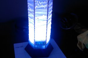
- LED and buzzer notifications
- Bluetooth communication
After startup, the system enters manual mode. The OLED displays Bluetooth status, battery voltage, manual countdown time, and jump count.
In manual mode:
Button 1
- Single click: increase countdown time
- Double click: decrease countdown time
- Long press: restore default time
Button 2
- Single click: start countdown and jump counting
- Double click: cancel countdown
- Long press: switch between automatic detection mode and manual countdown mode
Firmware Source Code
#include "bflb_mtimer.h"
#include "bflb_i2c.h"
#include "board.h"
#include "u8g2.h"
#include <freertos.h>
#include "task.h"
#include "bflb_gpio.h" //包含GPIO库文件
#include "key_manager.h"//按键处理
#include "bflb_adc.h"//adc
#include "log.h"
#include "bluetooth.h"
#include "conn.h"
#include "conn_internal.h"

#include "btble_lib_api.h"
#include "bl616_glb.h"
#include "rfparam_adapter.h"

#include "gatt.h"
#include "ble_tp_svc.h"
#include "hci_driver.h"
#include "hci_core.h"
BFLOG_DEFINE_TAG(MAIN, "MAIN", true);
bool ble_connected_flag = false; // 蓝牙连接状态标志
...
Read more »