In my
implementation, I placed great emphasis on good gamma correction so that the brightness curve appears as linear as possible. For
this purpose, I created logarithmic correction tables that counteract
the inverse logarithmic brightness perception of the eye and
compensate for it.
Fechner's law states that the subjective sensation is proportional to the logarithm of the stimulus intensity. According to this law, human perceptions of sight and sound work as follows: Perceived loudness/brightness is proportional to logarithm of the actual intensity measured with an accurate nonhuman instrument. [Wikipedia]
These correction tables cover all 256 brightness values, which is obviously excessive when only 15 steps are displayed. I use this type of gamma correction in all my projects and had already calculated the tables.
Without gamma correction, the brightness increases very quickly at the beginning with a linearly increasing PWM duty cycle and then changes only very slowly later on – pay attention to this, unfortunately you can see this poor dimming curve everywhere. The impression for the human eye in this case is shown with the red curve.
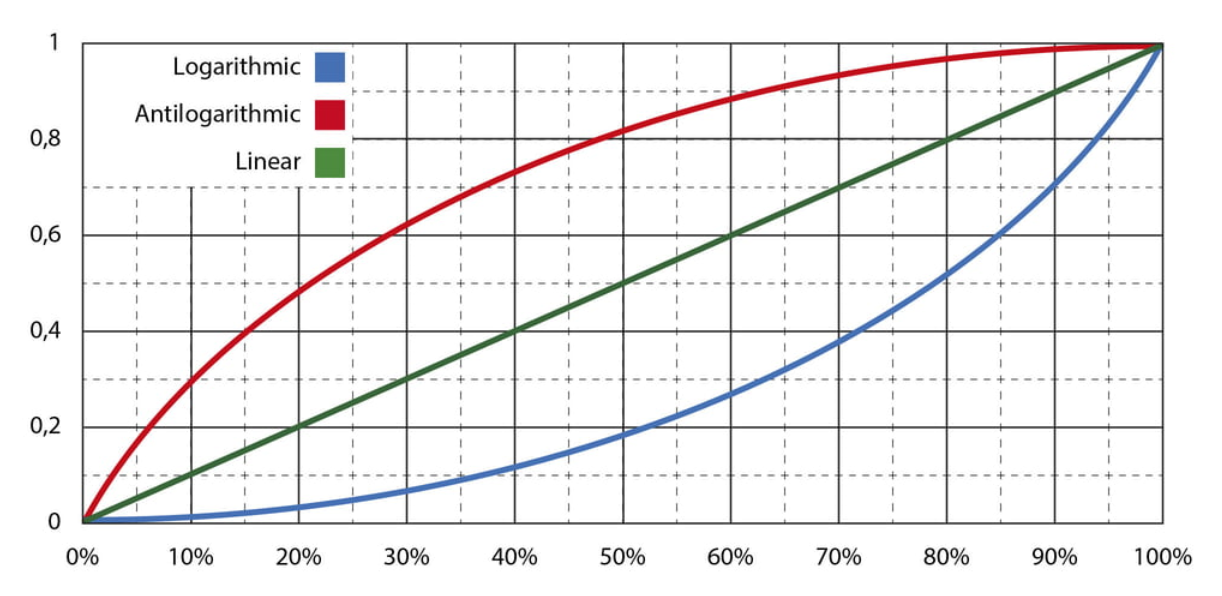
The blue curve shows how the PWM duty cycle increases with evenly rising brightness setpoints: very slowly at first, then faster and faster.
The perceived brightness impression can finally be seen in the green curve - ideally completely linear.
Unfortunately, this perception depends on many environmental factors such as external brightness, color, and probably also on the individual.
In the code, strange correction factors can be seen in the RGB values for the quarter-hour LED. Here, I correct the slightly different color impressions of the WS2812 LED modules.
I have built numerous variants of this project, in different designs and appearances.
The code isn't particularly pretty—it works for me.
I bought the case with the eight adjacent light surfaces at a flea market. In front of the surfaces is a sliding collecting lens. I suspect that it was a light box used to enlarge X-ray films.
The clock uses a Dallas RTC module DS3231. It also features this yellow box from electronic scrap with a rotary encoder and LCD, which can be used to set the time. A version with GPS synchronization is in the works.
#include <Wire.h>
#include <TimeLib.h>

//#include <DS1307RTC.h>
#include "RTClib.h"
RTC_DS3231 rtc;

#include <LiquidCrystal_I2C.h>
LiquidCrystal_I2C lcd(0x27, 20, 4); // set the LCD address to 0x27 for a 16 chars and 2 line display

#include <RotaryEncoder.h>
#define PIN_IN1 2
#define PIN_IN2 3
#define buttonPin 6
// Setup a RotaryEncoder with 2 steps per latch for the 2 signal input pins:
RotaryEncoder encoder(PIN_IN1, PIN_IN2, RotaryEncoder::LatchMode::TWO03);

#include <FastLED.h>
#define NUM_LEDS 8
#define DATA_PIN 4
#define CLOCK_PIN 5
// Define the array of leds
CRGB leds[NUM_LEDS];

// gamma 1,5
const uint8_t PROGMEM gamma8[] = {
  0, 0, 1, 1, 2, 2, 3, 3, 4, 4, 4, 5, 5, 6, 6, 7, 7, 8, 8, 9, 9, 10, 10, 11, 11, 12, 12, 13, 13, 14, 14, 15, 15, 16, 16, 17, 17, 18, 18, 19, 19, 20, 21, 21, 22, 22, 23, 23, 24,
  25, 25, 26, 26, 27, 27, 28, 29, 29, 30, 30, 31, 32, 32, 33, 34, 34, 35, 35, 36, 37, 37, 38, 39, 39, 40, 41, 41, 42, 43, 43, 44, 45, 46, 46, 47, 48, 48, 49, 50,
  51, 51, 52, 53, 53, 54, 55, 56, 56, 57, 58, 59, 60, 60, 61, 62, 63, 64, 64, 65, 66, 67, 68, 68, 69, 70, 71, 72, 73, 74, 74, 75, 76, 77, 78, 79, 80, 81, 82, 82, 83,
  84, 85, 86, 87, 88, 89, 90, 91, 92, 93, 94, 95, 96, 97, 98, 99, 100, 101, 102, 103, 104, 105, 106, 107, 108, 109, 110, 111, 112, 114, 115, 116, 117, 118,
  119, 120, 121, 123, 124, 125, 126, 127, 128, 130, 131, 132, 133, 134, 136, 137, 138, 139, 141, 142, 143, 144, 146, 147, 148, 150, 151, 152, 154, 155,
  156, 158, 159, 160, 162, 163, 164, 166, 167, 169, 170, 172, 173, 174, 176, 177, 179, 180, 182, 183, 185, 186, 188, 189, 191, 192, 194, 196, 197,
  199, 200, 202, 204, 205, 207, 209, 210, 212, 214, 215, 217, 219, 220, 222, 224, 226, 227, 229, 231, 233...
Read more »
 Hulk
Hulk
 Setvir
 Sagar 001
 mihai.cuciuc