 nobcha
While researching the origin of this LC meter approach, I found that the core idea is much older than microcontrollers.
The oscillator itself traces back to the 1920s, when Mr. Franklin at Marconi described what is now known as the Franklin oscillator: an LC resonator combined with a phase-inverted amplifier.
‐The history
Much later, in 1988, Dr. Hegewald in East Germany applied this principle to an LC meter concept using a microcontroller. This idea was later popularized by Neil Heckt through AADE, where he sold LC meter kits and openly shared both the circuit and the PIC firmware. The design was also described in detail by Phil Rice (VK3BHR) in an Australian amateur radio magazine.
What fascinated me is not absolute accuracy, but how naturally this circuit maps an analog impedance problem into a frequency domain that a microcontroller can handle very well. By focusing on differential measurements and a known reference capacitor, the system becomes simple, transparent, and easy to verify.
I’ve noticed that many builds closely replicate the original AADE design, which is perfectly valid. However, fewer people seem to change both the analog front end and the microcontroller itself.
By simplifying the implementation and using Arduino, my goal was to make such experimentation easier. In one case, this approach even led someone to re-implement the design again using a PIC, after first studying both versions.
This project is my attempt to revisit that idea with modern low-cost MCUs, while keeping the same spirit of simplicity and openness.
‐The principle
I think the principle behind this meter is very clever.
An additional element is temporarily added to the LC resonant circuit, and the oscillation frequency is measured. By comparing this frequency with that of the original LC circuit, the value of the added element can be derived by solving a simple set of simultaneous equations.
The measurement is divided into two steps. In the calibration step, a high-precision reference capacitor is added to the LC tank to determine the base LC parameters. In the measurement step, the element under test is added instead, the frequency is measured again, and its value is calculated from the difference.
By relying on frequency differences rather than absolute values, this approach naturally reduces errors caused by stray inductance and parasitic effects.
‐LTSpice simulation
First, I used LTSpice analysis to verify that the Franklin oscillator circuit works with an LC tank circuit and an inverting amplifier using a 74HCU04. I imported the .asy and .lib files related to the 74HC and performed a simulation as follows: https://nobcha23.hatenablog.com/entry/2021/12/31/153804
(1) Download the schematic from the link below and place it in the LTspice sym folder under the file name 74hcu04.asy.
http://ltwiki.org/files/LTspiceIV/lib/sym/Dig_Add/74HC/74hcu04.asy
This will become the circuit diagram data, and it will appear when you select it in the Component menu.
(2) Import the simulation data from the following location into the 74HC-related directory using 74HC.lib:
http://ltwiki.org/files/LTspiceIV/lib/sub/74hc.lib
Specify it as available for calling via Edit → SPICE Directive. (This is referenced when 74hcu04.asy calls the 74hcu04 simulation data.)
.lib 74hc.lib
(3) 74hcu04.asy requires an external power supply of 5V via "Vcc." Add a DC power supply and specify Vcc.
(4) Oscillation will not start unless initial operating conditions are set, so I set .ic V(n003) = 1V in Edit → SPICE Directive.
The circuit diagram for simulation is as follows.
LCM_FRANCLIN_HCU04_HC.asc
- The sketch overview
To count the frequencies: start measurement
→ wait for stable oscillation
→ count pulses for gate time "To refer FreqCount Library"
→ average N times until the adjacent frequencies are within 0.5%
→ output frequency
Calibration flow
→ measure freq1
→ insert Cref by turning on the relay
→ measure freq2
→ solve L,C of base tank
→ store parameters
Measuring flow
→ insert DUT
→ measure freq3
→ calculate DUT value
→ display result
Please check the sketch in details.
https://github.com/Nobcha/ArduinoLCM/blob/main/lc_meter_v_64.ino
-Printed Circuit Board Design
I used KiCAD to design the printed circuit board pattern. Starting KiCAD and selecting "Nano" under "Create a new project from template" will provide both the Arduino Nano circuit and the PCB pattern. This is convenient. I used digital transistors. A standard PNP transistor can be used by adding a base bias resistor. I edited an existing relay symbol to match the Panasonic TQ relay I was using, and used the DIP_10_w7.62 footprint. The Arduino and 74HCU04 were socketed. I uploaded the Gerber data and bill of materials for the finished printed circuit board to GitHub. https://github.com/Nobcha/ArduinoLCM/blob/main/LCM_NANO.zip
https://github.com/Nobcha/ArduinoLCM/blob/main/LCM_NANO_BOM.pdf
-Replaced the display
The LCD is connected via I2C, so I replaced it with an OLED 128x64 and rewrote the sketch. I uploaded it to GITHUB as V6.4.
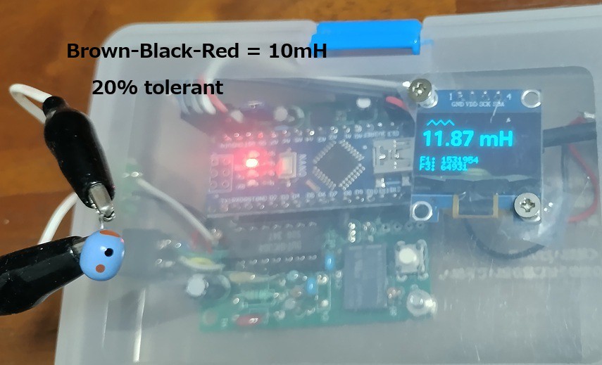
V6.4@GITHUB: https://github.com/Nobcha/ArduinoLCM/blob/main/lc_meter_v_64.ino
BLOG:https://nobcha23.hatenablog.com/entry/2025/07/30/230715
PCB:https://www.pcbway.com/project/shareproject/LC_meter_of_using_the_franclin_oscillator_9b1ebd81.html
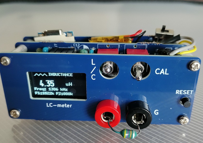
- DPDT switch version
I made a prototype circuit using a double-pole double-headed switch instead of a relay. The CPU used was ATmega328P.
Problems with relays: Cost
Advantages of DPDT switches: Availability (6P double-pole double-throw), cost, reliability
Disadvantages: No automatic calibration
I think "manual calibration is a feature, not a bug"
V8@GITHUB https://github.com/Nobcha/ARD_LCM_MANUAL
BLOG: https://chitose6thplant.fc2.page/lc-meter-v7-dpdt-calibration-3-steps-layers-pcb-model/