 nobcha
In earlier versions of this LC meter (up to V6), calibration was handled automatically by a relay. The relay would insert the reference capacitor into the tank circuit at the start of each measurement session. Simple, automatic — but not without problems.
Problems with the relay approach
Cost: small signal relays suitable for ~1.5 MHz switching are not cheap
Availability: sourcing a consistent relay across builds was annoying
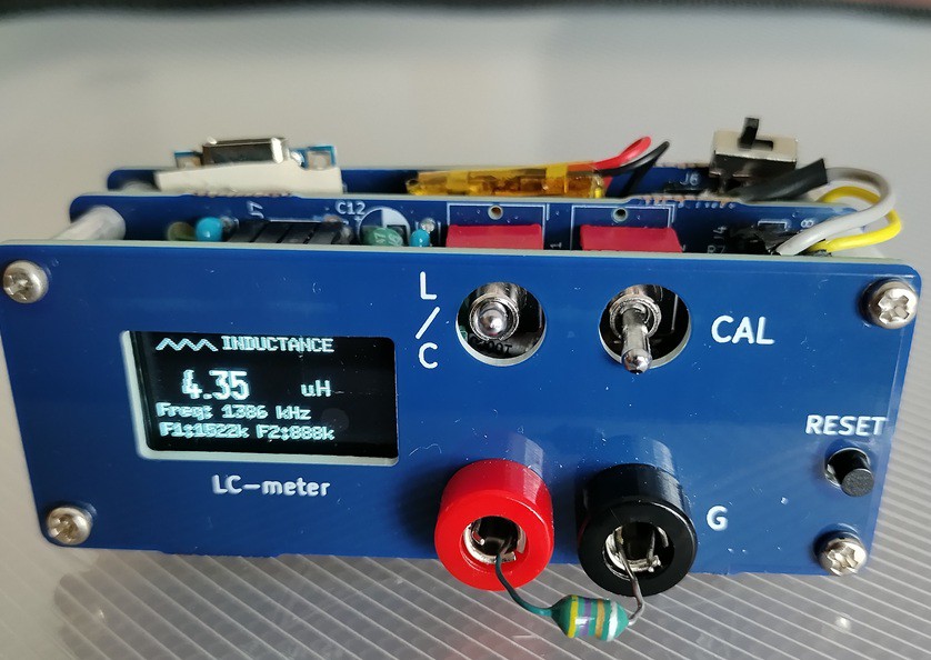
The V7 solution: a 6P DPDT switch
I replaced the relay with a readily available 6-pin double-pole double-throw (DPDT) switch. The switch physically inserts or removes the reference capacitor from the LC tank — the same function, but done by hand.
This makes calibration a conscious 3-step manual operation:
Set switch to CAL position
Press the calibration button — the sketch measures f1 and f2, solves for L and C of the tank
Set switch to MEASURE position — ready to use
"Manual calibration is a feature, not a bug"
Once you understand that calibration only needs to be done once per power-on (or when ambient temperature changes significantly), the manual switch becomes perfectly acceptable. In fact, it makes the measurement process more transparent — you always know exactly what state the circuit is in.
The sketch for V7 is available on GitHub, along with the KiCad PCB files and assembly manual (English and Japanese):
👉 https://github.com/Nobcha/ARD_LCM_MANUAL
A detailed build log is also on my blog:
👉 https://chitose6thplant.fc2.page/lc-meter-v7-dpdt-calibration-3-steps-layers-pcb-model/
One note on the PCB
The first version of the V7 PCB had three errors (OLED header pinout, R6/R7 silkscreen, ICSP header). These are documented in the repository as a "Mistake prevention list." A corrected schematic is also included.
Next up: V8, where the sketch was restructured to reduce flash usage from 95% down to 80%, making room for future improvements.
kpa radio ©nobcha
Discussions
Become a Hackaday.io Member
Create an account to leave a comment. Already have an account? Log In.