 Profe Tolocka
Programming
In the third part of this tutorial, we focused on the refresh process of EPDs and what it means for using these displays
In this fourth part, we will look at the hardware and software components needed for an EPD project. We’ll take a closer look at the features of the EE04 board, how to configure the Arduino IDE to use it, and what programming options are available. Finally, we’ll explore the Seeed_GFX library in detail, including how to install it and how it works.
Hardware and Software
Every project, whether it includes an EPD or not, consists of two main components that work together: hardware and software. Let’s take a look at the hardware and software components you need to create a project with an EPD, and what options are available.
Hardware
What hardware do you need to create a project with an EPD?
Obviously, you’ll need an EPD display—but which one? What features should it have?
The choice of display will depend a lot on the project you want to build. You’ll need to decide whether it should be monochrome or color, as well as its size and resolution.
If your project needs to display information that changes frequently, you’ll need a display that supports fast or partial refresh. On the other hand, if the information doesn’t change or only changes very rarely, refresh speed won’t be a limiting factor.
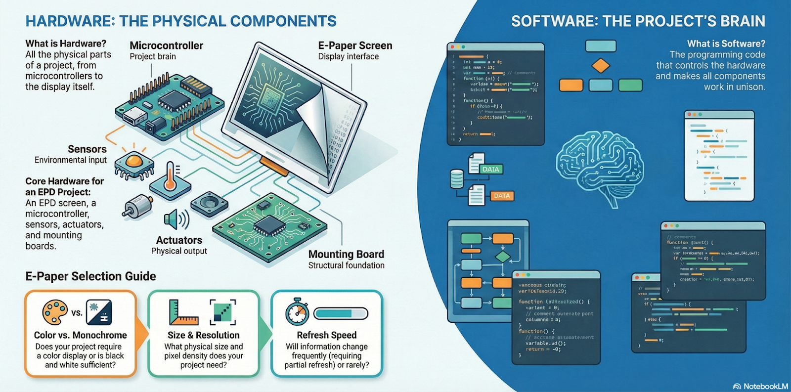
And besides the display itself, you’ll also need a board to control it. For this, you can design your own board from scratch, or use a ready-made solution, like the driver boards we discussed in previous chapters.
One of the most interesting driver boards I’ve tested—thanks to its rich set of features—is the EE04 from Seeed Studio, and that’s the one we’ll use in the example projects. So, the next step in our journey will be to take a closer look at its features and capabilities.
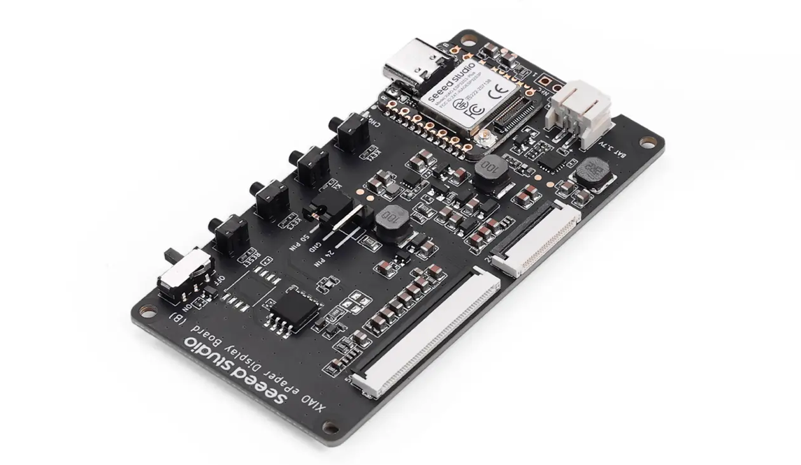
The EE04 Board
The EE04 is one of the EPD controller boards offered by Seeed Studio. In addition to supporting a wide variety of displays, the EE04 features excellent wireless connectivity, multifunction buttons, and all the circuitry needed to create battery-powered applications.
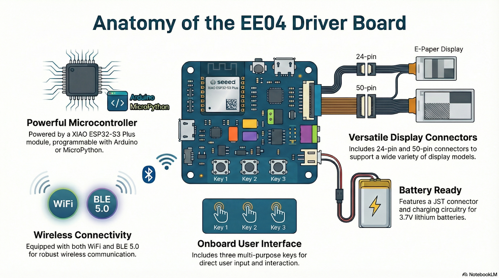
The brain of the EE04 is a XIAO ESP32-S3 Plus module, which has enough power to develop everything from the simplest to the most complex applications. Like all XIAO modules, the ESP32-S3 Plus can be programmed in different languages, such as Arduino or MicroPython.
In our case, we’ll use the Arduino environment for software development. This choice is because Arduino offers very complete and mature support, along with a large and active user community.

At this point, we’ve made two key decisions: we’ll use the EE04 to control the EPD, and we’ll program it using Arduino. This defines the platform we’ll use for the upcoming projects.
We’ll look at other programming options soon, but whichever one you choose, you’ll first need to set up the Arduino IDE—which is what we’ll do next.
Setting Up the Arduino IDE
Before we start programming, we need to configure the Arduino IDE to work with the EE04 board—specifically with the XIAO ESP32-S3 Plus it contains.
We’ll use version 2 of the IDE, which is the latest at the time of writing. If you don’t have it installed, you’ll need to download it from the Arduino website and install it on your computer.
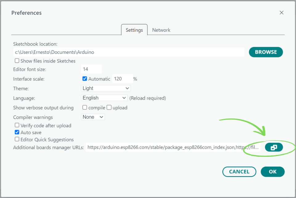
With the IDE installed, you have to add support for the XIAO S3 Plus through the Board Manager. This is a straightforward process. First, open the IDE preferences by selecting File and then Preferences from the menu (or press Ctrl + ,), and click the icon shown in the image:
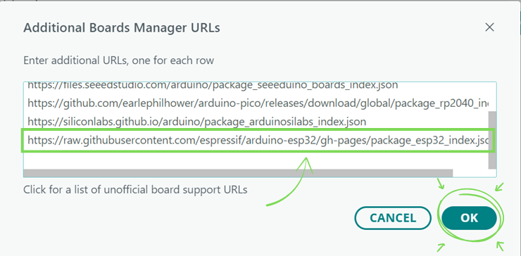
In the Additional Boards Manager URLs window that opens next, add the following address and click OK:
https://raw.githubusercontent.com/espressif/arduino-esp32/gh-pages/package_esp32_index.json
Click OK again in the Preferences window.
Now, in the toolbar on the left side of the IDE, select the Board Manager. In the search box, type “ESP32.” You’ll see the installer for the package that supports various ESP32-based boards. Click INSTALL.
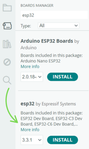
After a few minutes of downloading and installation, the IDE will be ready to program the board.
Connect it with a USB cable and select the board and the port using the selector at the top left:
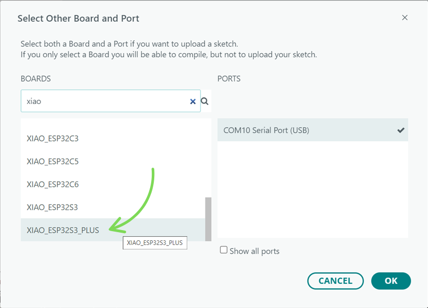
Click OK and you’re done! Your Arduino IDE is now ready to program the XIAO ESP32-S3 Plus.
Checking Everything
It’s a good idea to check if everything is working correctly by uploading a sample program.
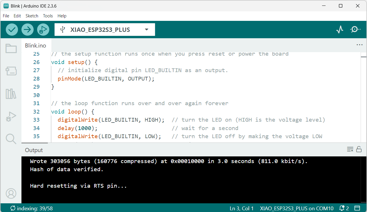
To do this, go to the menu, select File → Examples, and choose Basic → Blink.
A new window will open with the test code that makes the onboard LED blink every second. Click the UPLOAD button, and after a few moments, the LED should start blinking.
Congratulations!
You’ve just taken the first step by getting the IDE ready to start programming the EE04 board.
Upload issues
In rare cases, you may run into problems when uploading a sketch to the board. The serial port might disappear, or it may still be visible but throw an error during the upload process.
To fix this, you need to put the XIAO module into bootloader mode using one of the following methods.
Method 1
- Disconnect the USB cable to power off the board.
- Press and hold the B (Boot) button on the XIAO.
- While holding B, reconnect the USB cable to power the board.
- Release the B button.
Method 2
- With the board connected and powered, press and hold the B button.
- Press the R (Reset) button once.
- Release both buttons (B and R).
After that, upload the Blink example again to verify that the board is responding correctly.
Software
OK, with the EE04 board ready, how do you start writing code for that awesome application you have in mind?
There are several paths you can take when programming an application for an EPD, depending on many factors—like the complexity you want to achieve and the level of control you need over the display.
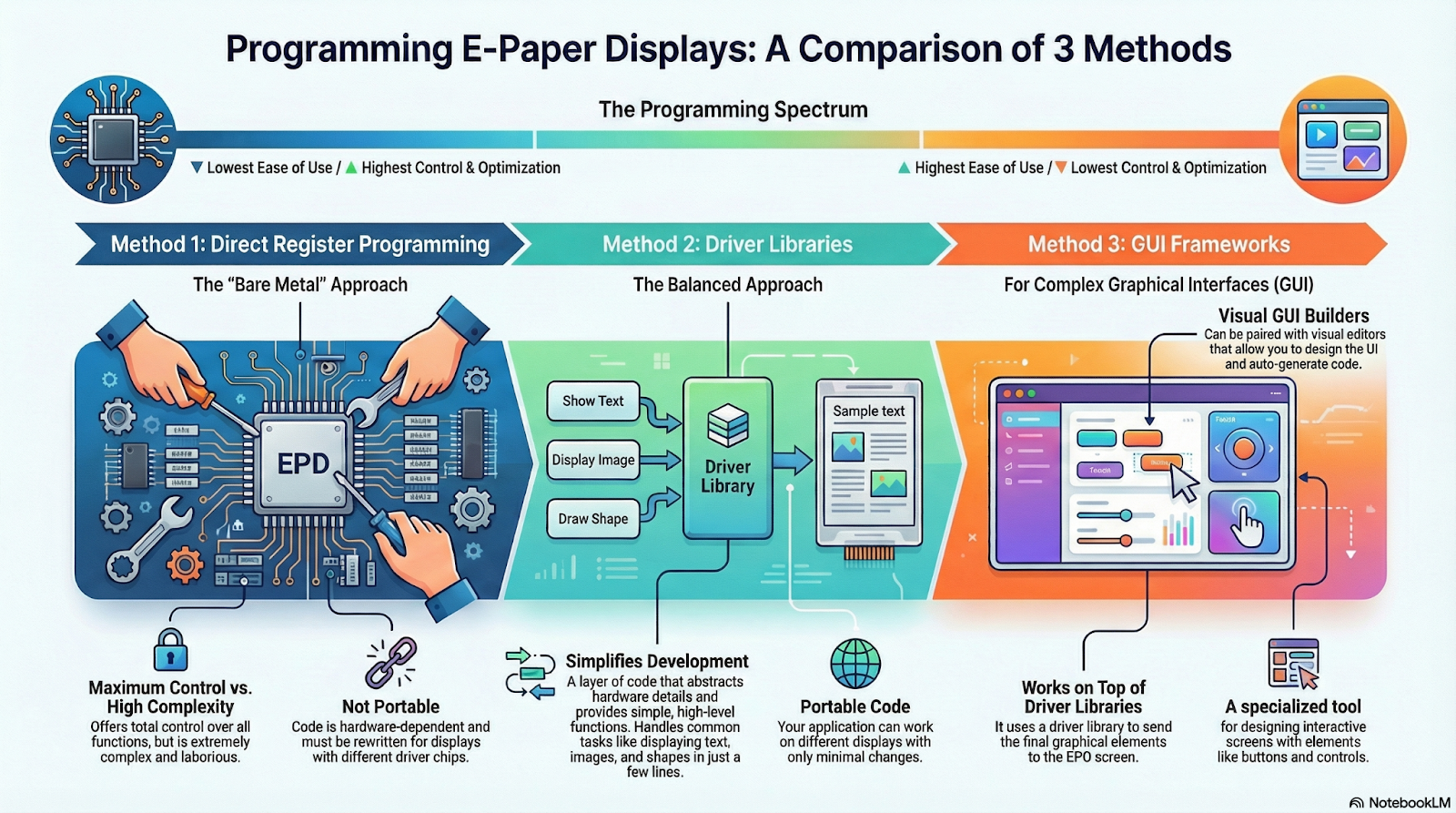
To make things simple, I’ve grouped these options into three main categories: Register-Level Programming, Driver Libraries, and GUI Frameworks. Let’s see what each one is about.
Register-Level Programming
This approach involves controlling the EPD by directly accessing the internal registers of the driver chip, making it the most complex and demanding way to program.
It requires a detailed understanding of the driver’s operation, since its registers—memory locations that receive commands and data—define all the panel’s functions, such as reset, low-power mode, LUT management, RAM access, or reading the temperature sensor.
Below is just a snippet from a sample program provided by GoodDisplay for one of their EPDs that uses an SSD1680 chip as the controller. The code accesses its registers directly.

As you can imagine, trying to create an application that displays text, images, and shapes using this method will give you a major headache—you should avoid it unless it’s your only option.
Also, the code you write will only work for that specific driver and not for others, meaning it’s not portable. If you need to create an application for another EPD with a different driver, you’ll have to rewrite all the code from scratch, since each driver has its own set of registers and different functions.
The only real advantage of this programming method is that you get complete and total control over the display and all its features.
Driver Libraries
To avoid the complexity of controlling the driver chip directly, driver libraries are used. These libraries abstract away the hardware details and offer high-level functions for common operations like displaying text, images, or graphics.
They act as an intermediate layer between your application and the panel, sending the necessary commands to the driver internally. Some of the most commonly used libraries are Seeed_GFX, and GxEPD2.
Below is a complete example program that displays “Hello world!” on a 5.83-inch monochrome display using Seeed_GFX:
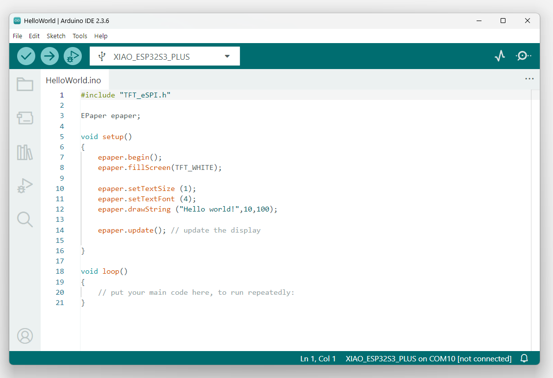
The advantage of using a library like this is obvious: in less than 10 lines of code, you can initialize and clear the display and show text with a specific font and size. Plus, the code is portable, since with just a few configuration changes, it can be adapted to different displays and controller boards.
The details of how it works will be covered later on in the example projects.
GUI Frameworks
When working with EPD displays, a big part of the job is designing the graphical user interface (GUI). In addition to basic graphics libraries, there are specialized GUI frameworks that make this task much easier. One of the most popular is LVGL, which can run on resource-limited devices like the ESP32. LVGL handles the display of graphical elements (widgets) and manages user interaction through buttons or touchscreens.
LVGL does not control the EPD directly. Instead, it renders all the widgets to a memory buffer, which then needs to be sent to the EPD using another library, such as Seeed_GFX. LVGL acts as a software layer on top of the driver library and relies on its capabilities.
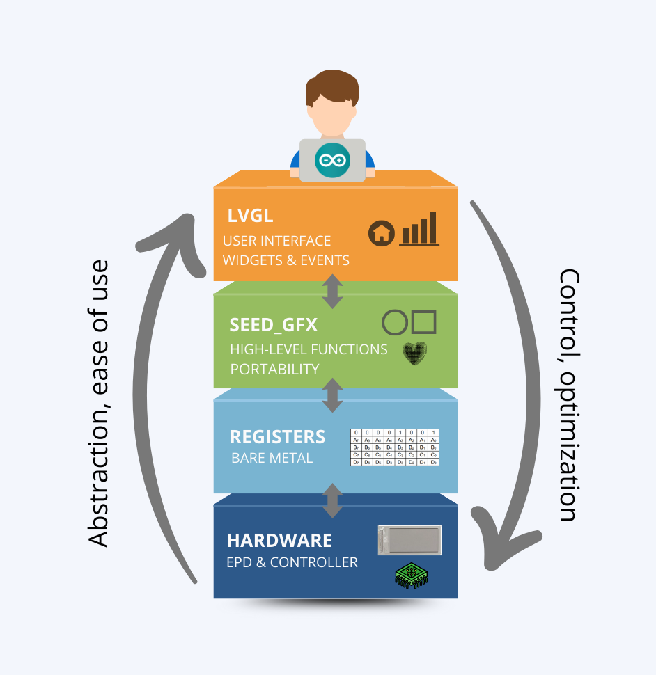
Each additional layer provides more abstraction than those below it, making tasks easier and hiding hardware details. On the other hand, you also lose direct control over the internal operation, which can reduce the level of optimization.
Below is a code snippet that displays “Hello world!” on the screen. Although it’s not really worth using LVGL for something this simple, I’m using the same example as before just for comparison purposes.
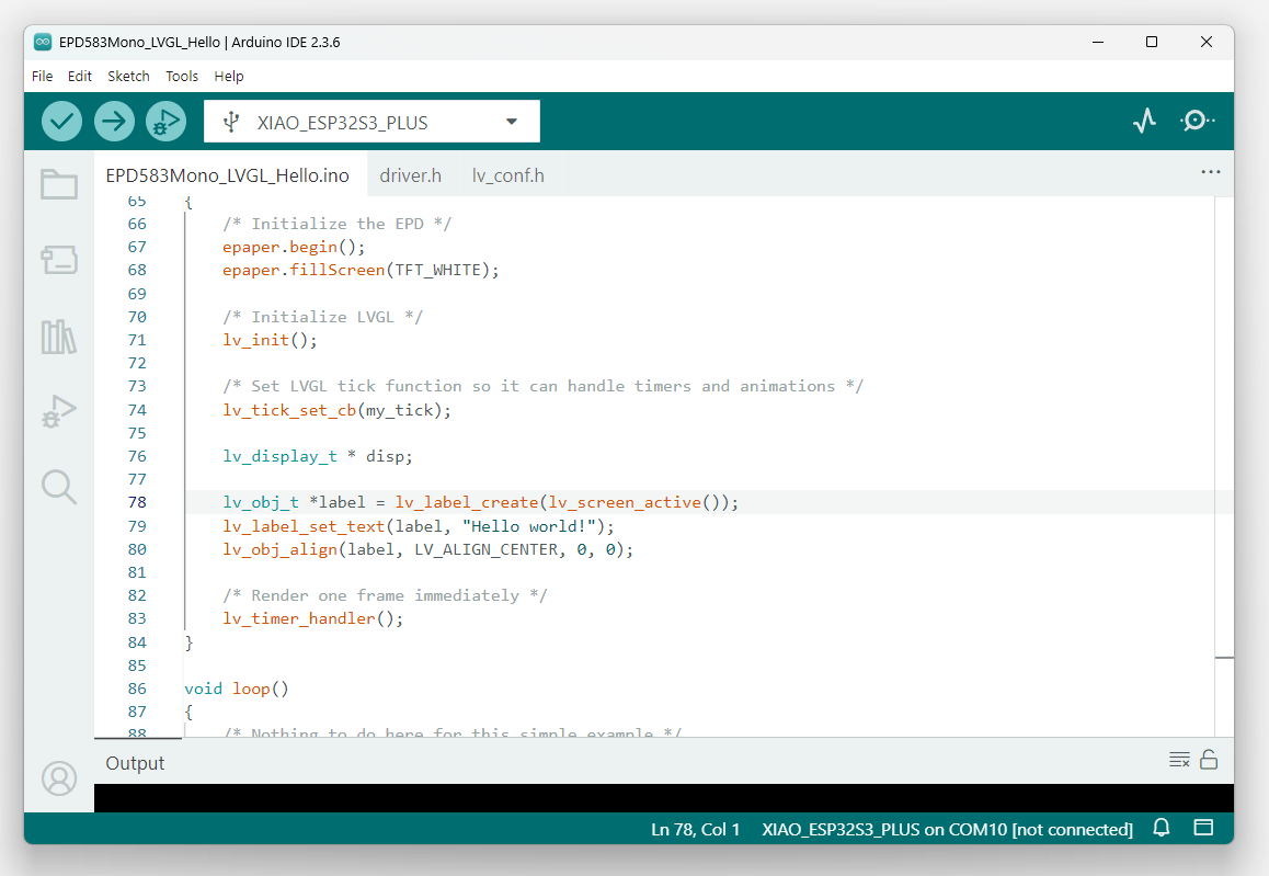
The code required by GUI frameworks is usually more complex than that of simple graphics libraries. To make development easier, there are GUI builders—visual editors that let you design the interface graphically and then automatically generate the necessary code. LVGL can be integrated with tools like LVGL Pro or EEZ Studio, which we’ll look at later on.
No-code tools
If you don’t want to program, or if you want to quickly create a prototype for testing, you can also use SenseCraft HMI, a powerful no-code tool that allows you to build applications without writing a single line of code.
SenseCraft HMI works as a web-based platform and lets you create visual interfaces and dashboards using a set of pre-designed templates for different applications such as calendars, image galleries, or weather forecasts.
You can also create a template from scratch by adding elements like RSS news, web content, device sensors, and more.
You can access it by creating a free account at: https://sensecraft.seeed.cc/hmi
The Seeed-GFX Library
Previously, we briefly mentioned this library as an example of the driver libraries you can use to control an EPD. From here on, we’ll take a closer look at it, since it will be the main library used for all projects in this second part of the tutorial.
Features
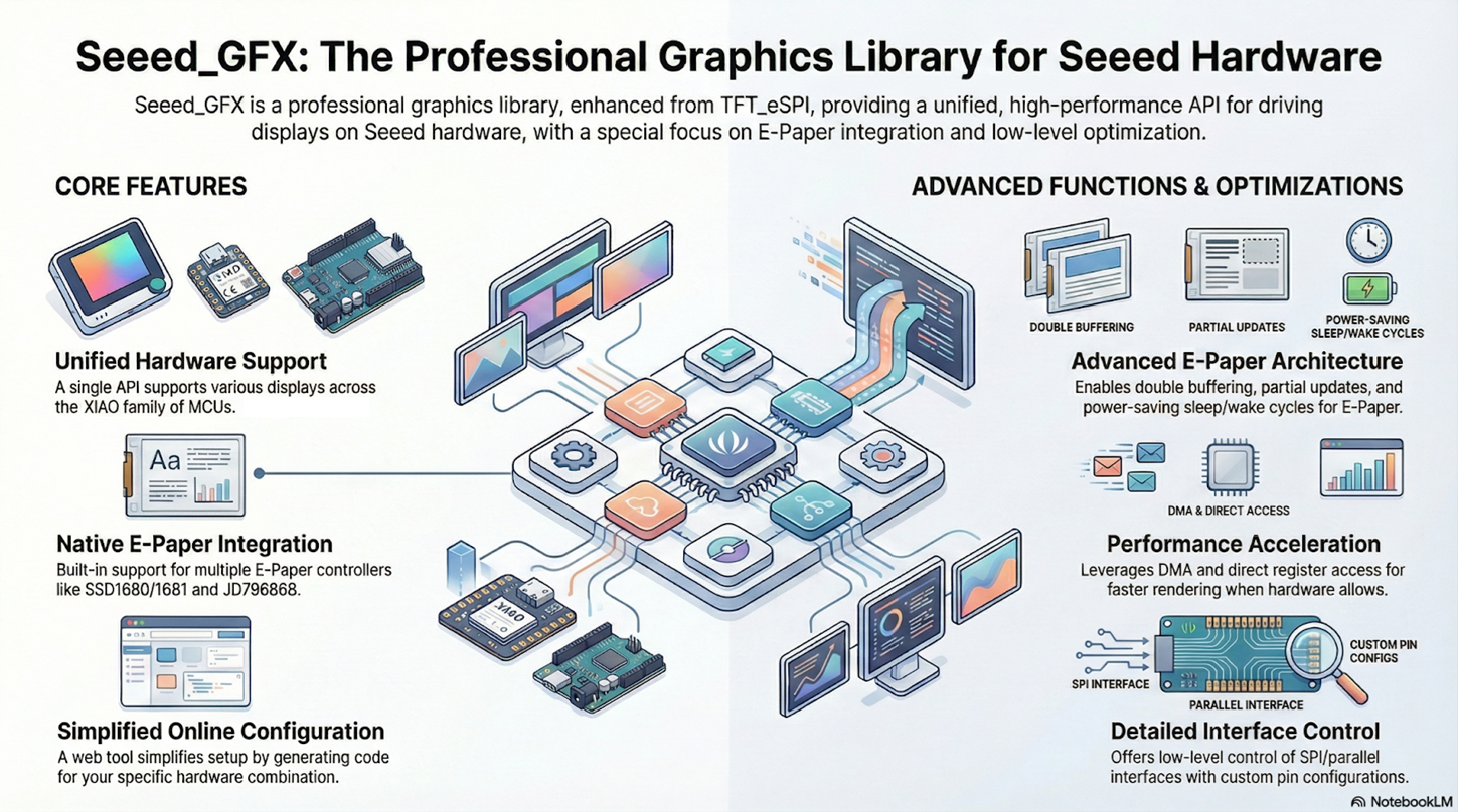
Seeed_GFX is a versatile graphics library developed by Seeed Studio, based on the popular TFT_eSPI library. It’s designed to control TFT, OLED, and EPD displays. The main difference from the original library is native support for ePaper (EPD) displays and special optimizations for Seeed Studio’s hardware ecosystem, like the XIAO modules.
The library is compatible with both Arduino and PlatformIO, includes advanced power management for battery-powered projects, and offers an online configuration tool that makes it easy to generate code for your specific hardware. For EPDs, it implements partial refresh, optimizing update times.
Installation
Before you can use the Seeed_GFX functions, you’ll need to install the library in the Arduino IDE.
The installation process is super simple: just download the compressed file from the official repository and extract it into the IDE’s libraries folder.
To download it, go to the repo (https://github.com/Seeed-Studio/Seeed_GFX), click the Code button, and then choose Download ZIP.
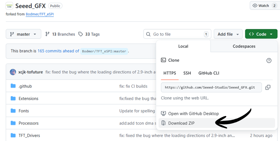
A compressed file named Seeed_GFX-master.ZIP will be downloaded.
Next, you need to extract this file into your Arduino IDE’s libraries folder.
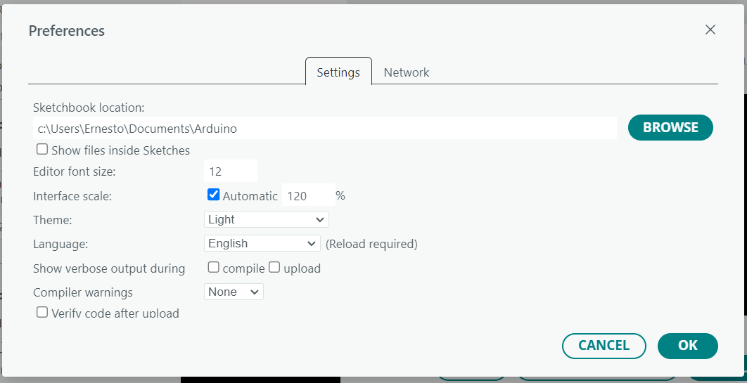
If you’re not sure where that is, open the Arduino IDE, go to File > Preferences, and look for the path shown under “Sketchbook location.”
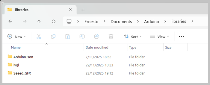
Extract the library into a folder named Seeed_GFX inside the libraries folder you found in that path.
That’s it! You’re all set.

To check if the library was installed correctly, open the Arduino IDE and go to Sketch > Include Library—you should see Seeed_GFX listed near the bottom.
You’ll also find lots of examples under File > Examples, and at the end, there will be a Seeed_GFX section.
How it Works
Using Seeed_GFX with EPDs brings some unique characteristics directly related to ePaper technology. Understanding these details is key to knowing how the code flow works with this library—and to using it correctly.
Take a look at the following code. It’s a simple example that shows the text “Hello” at a specific position on the screen:
#include "TFT_eSPI.h"

EPaper epaper;

void setup()
{
  epaper.begin();

  epaper.fillScreen(TFT_WHITE);

  epaper.drawString ("Hello",10,10);
  epaper.update(); // update the display
}

void loop()
{
// put your main code here, to run repeatedly:
}
The first thing the code does is include the TFT_eSPI library, which is the base for Seeed_GFX.
Then, it creates an object called epaper from the EPaper class. This object will be linked to the display, and it’s the one you’ll use to call all the methods to interact with the EPD.
After that, there are a few instructions inside the setup() function:
- begin: Initializes the display, sets up the connection with the EE04, and prepares all internal structures and buffers.
- fillScreen: Fills the display with white pixels (TFT_WHITE).
- drawString: Writes the text (“Hello”) at a specific coordinate.
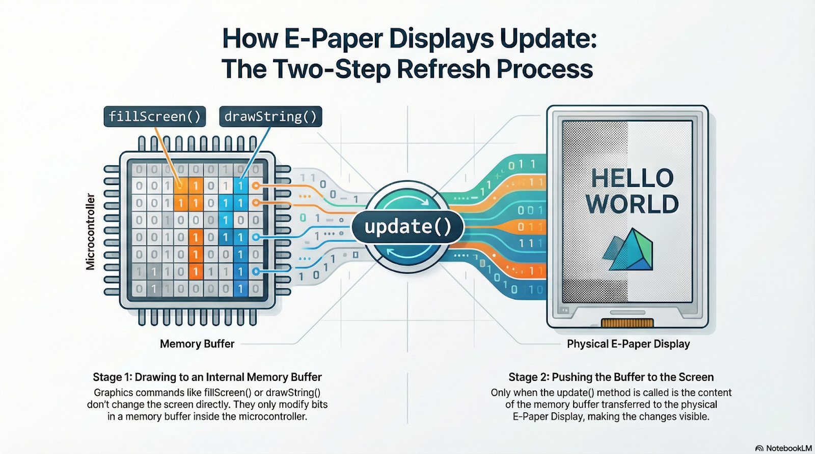
- update: Refreshes the screen to show the result of all the previous methods. This last step is crucial to understand.
Unlike an OLED or LCD display—where each graphics instruction is immediately visible—on EPDs, functions like fillScreen() or drawString() only affect an image buffer stored in RAM (in this case, on the ESP32 of the EE04 board).
These operations change the buffer without affecting what’s actually shown on the screen. Only when you call update(), the buffer’s content gets transferred to the display and the image is physically updated.
The update() function triggers the EPD refresh process, which means that millions of tiny particles physically move inside the panel to form the new image. This movement takes time (sometimes several seconds), and while it’s happening, the display can’t process new instructions.
That’s why EPDs have a special BUSY pin. The library (such as Seeed_GFX) uses this pin to check whether the screen is still updating. Before sending a new command—like updating text or drawing a new image—the library polls or checks the BUSY pin to make sure the display is ready. If it doesn’t wait, commands sent during the refresh process may be ignored or can even cause visual glitches.