 Profe Tolocka
Introduction
This project is an example of how to apply the concepts we covered in the previous parts of this tutorial. You can check them at the following links:
Do you remember the ePaper badge from the previous project? It was part of an imaginary scenario in which event organizers asked you to create a novel way to identify participants.
Continuing with that idea, let’s say they now have a new request: the event organizers are back with a new challenge — alongside the main exhibition, they will be hosting talks and conferences in different rooms, featuring various speakers
To keep the audience informed about what’s going on, they want to set up a sign at the entrance of each room. This sign should show the speaker’s photo, their name, and the topic of the talk. On top of that, the sign needs to show the current status of the session—whether it’s Scheduled, Ongoing, or Finished—as time goes by.
Here’s a sketch of what the organizers have in mind:
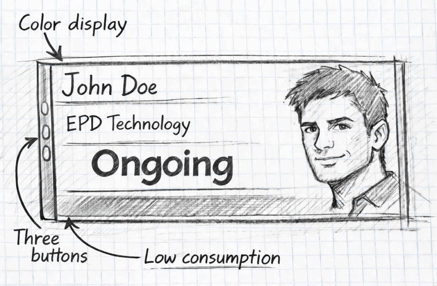
They’re looking for a screen with good visibility and the ability to change the session status by pressing one or more buttons on the side of the device.
Powering is another important point: although the devices will usually be plugged into a steady power source, they should have low power consumption so they can also run from a power bank if needed.
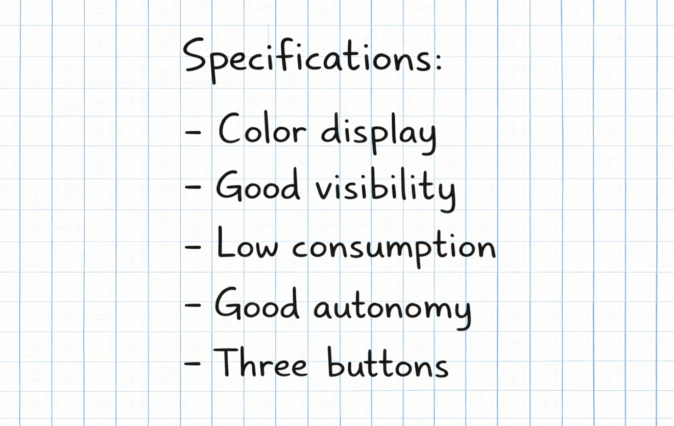
Here’s a quick summary of the requirements:
Component Selection
Let’s look at the requirements and choose the components for this project.
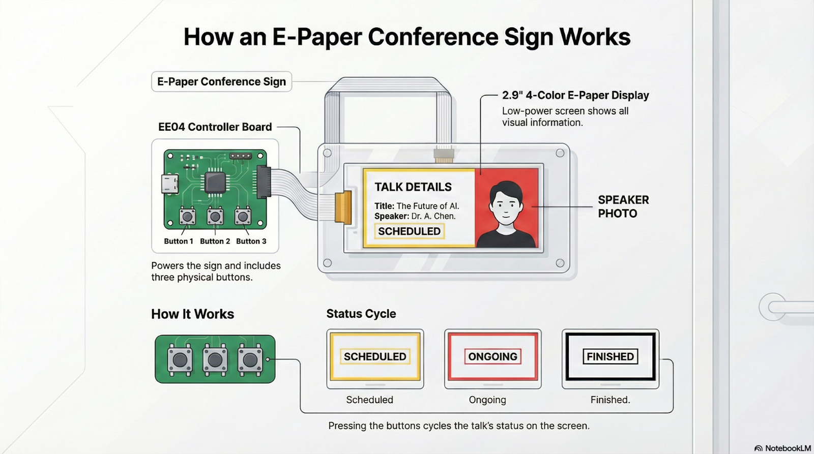
First, the display: It needs to have good visibility and low power consumption, since there’s a chance the device might be powered by batteries. An EPD (ePaper Display) is a perfect fit here because of its extremely low power usage.
Fast refresh isn’t necessary for this application, as the sign’s status won’t change frequently—so a color EPD like the one we used before is ideal.
We’ll also need physical buttons to change the sign’s status, and the EE04 board conveniently comes with built-in buttons, making it the perfect companion for the EPD.
So, for this project, we’ll use the same platform as before: an EE04 board combined with a 2.9-inch, four-color EPD.
Displaying Images
In this project, we need to display an image along with text. The Seeed_GFX library offers two main functions for this: drawBitmap and pushImage.
The drawBitmap function is intended for monochrome images (two colors) and is perfect for simple icons or logos. On the other hand, pushImage allows you to work with color or grayscale images, making it suitable for more detailed graphics like illustrations or photographs.
Since in this project we want to show a color photo of a person, we'll use pushImage.
In code, the function is used as follows:
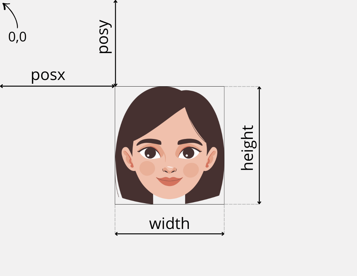
pushImage(posx, posy, width, height, imageData);
- posx and posy are the coordinates where the image will start to be drawn.
- width and height specify how many pixels wide and tall the image will be.
So far, it all seems pretty simple. But what does imageData mean in this function call? Is it the name of the image file, like "photo.jpg"?
Well, no. Here’s where things start to get a bit more complex.
What pushImage expects isn’t the name of an image file, but rather a series of data values that represent the image itself.
To really understand this, let’s review a few concepts about image formats and how color information is encoded.
Image Formats
A digital image is nothing more than a collection of pixels arranged in rows and columns, where each pixel has its own color.
The way this information is organized and stored—such as inside a file—is what we call the image format.
Over time, countless formats have appeared, each designed to meet different needs: some store the data “raw,” others use compression (with or without quality loss), some add transparency, metadata, and so on. That’s why we have such a variety: BMP, JPG, PNG, and many more.
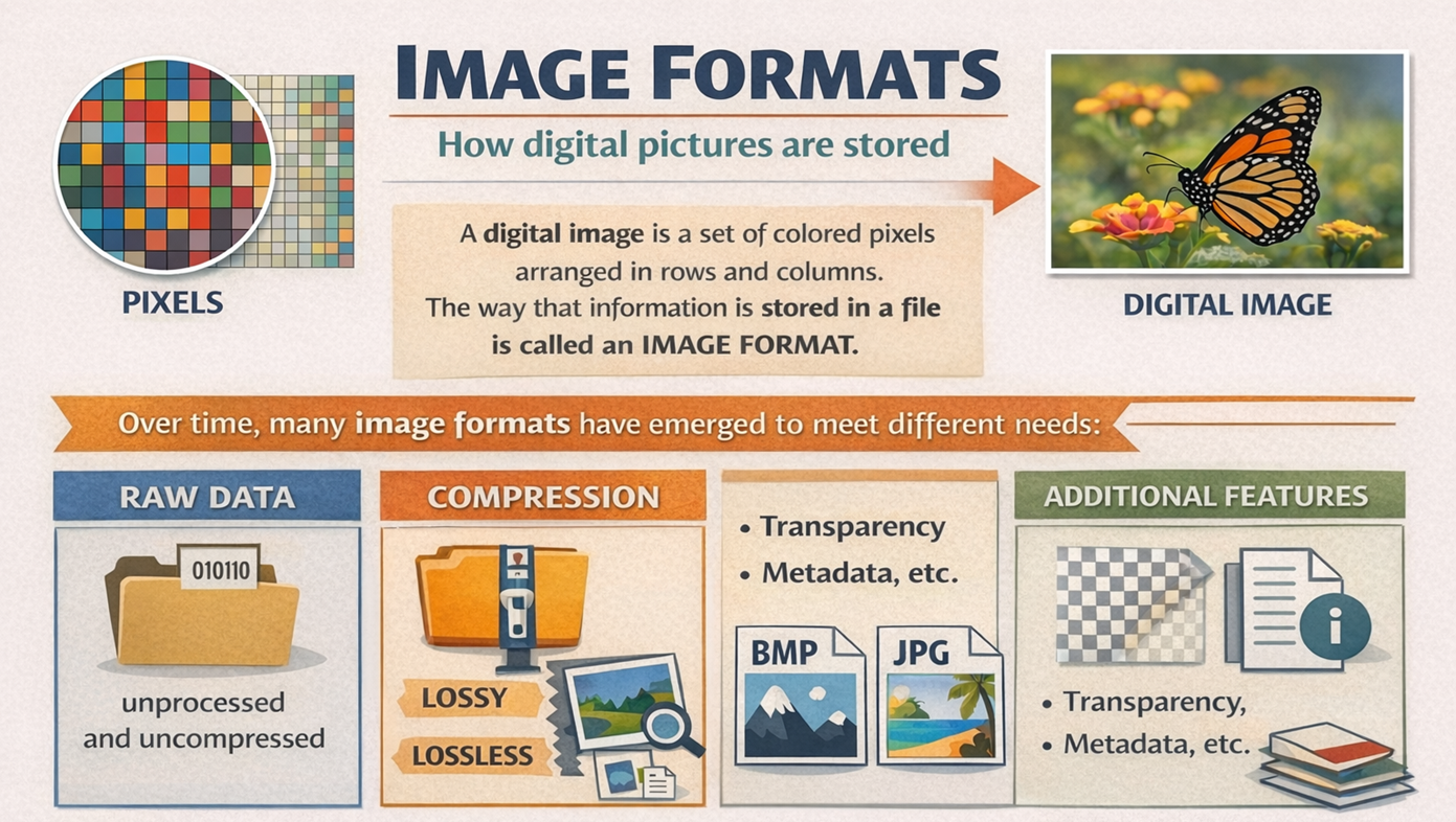
We won’t go deep into all those formats, but there’s one key concept you need to understand: how the color of each pixel is encoded. This is crucial for understanding how to display images on electronic screens in general—and on EPDs in particular.
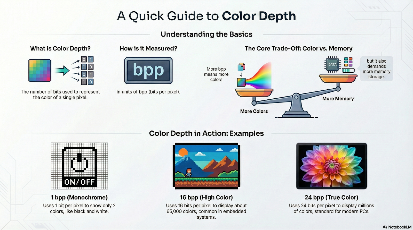
Color Depth
The number of different colors each pixel can display is called color depth, and it largely depends on the display technology and the available memory.
In embedded systems, it's common to find displays ranging from monochrome (only black and white) to TFT LCD screens that can show around 65,000 colors. On a computer, on the other hand, images typically use millions of colors, something possible thanks to the large amount of memory available.
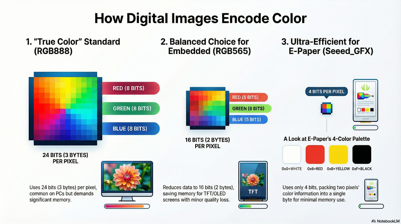
Color depth is measured in bpp (bits per pixel), meaning the number of bits needed to represent the color of each pixel. A monochrome image only needs one bit—so its color depth is 1 bpp—while a 65K color image requires 16 bpp, and computers commonly use 24 bpp.
The more colors each pixel can display, the more memory is needed to store the image. This isn’t a problem on a PC, but it becomes a significant limitation for microcontrollers, such as XIAO boards.
Color Encoding
On LCD or OLED screens, Seeed_GFX represents color information with 16 bpp (bits per pixel), using a format called RGB565. This name comes from the fact that it uses 5 bits for Red, 6 bits for Green, and 5 bits for Blue.
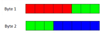
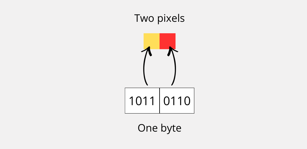
However, when using EPD displays, which support far fewer colors, Seeed_GFX employs a different, non-standard representation: it encodes color information using just 4 bits (4 bpp), so each byte can store the color of two adjacent pixels. This is very convenient, as it significantly reduces the amount of memory required.
The format works as follows: in each byte, the upper nibble (bits 4..7) holds the color code for the first pixel, and the lower nibble (bits 0..3) holds the color code for the second pixel.
On a 4-color EPD like the one we’re using in this project, these values are used to represent each color:
- 0x0 = WHITE -> 0000
- 0x6 = RED -> 0110
- 0xB = YELLOW -> 1011
- 0xF = BLACK -> 1111
You might have noticed that, to encode four color levels, only 2 bits per pixel (2 bpp) would be necessary—instead of four. And you’d be right! However, the designers of Seeed_GFX chose to use this format for consistency, even with EPDs that support different color depths, such as six-color panels.
Now we can clarify an important detail: in the imageData parameter, the pushImage function expects a byte array in which each byte contains the color information for two adjacent pixels—something like this:
const unsigned char image[] PROGMEM = {
  0x00, 0x00, 0x06, 0x06, 0x06, 0x06, 0x66, 0x66, 0x66, 0x66,
  0x6B, 0x6B, 0x6B, 0x6B, 0xBB, 0xBB, 0xBB, 0xB6, 0xB6, 0xB6,
  0xF6, 0xF6, 0xF6, 0xF6, 0x6F, 0x6F, 0x6F, 0x6F, 0xFF, 0xFF,
  0xFF, 0xFF, 0xFF, 0xF0, 0xF0, 0xF0, 0x00, 0x00, 0x00, 0x00
};
In the code snippet above, you can see the definition of the image array, which contains the information for all the pixels using the format we just discussed.
The PROGMEM directive tells the compiler that this data should be stored in Flash memory, rather than in RAM—which is typically much more limited on microcontrollers.
To illustrate how to use pushImage and the format of the array it expects as input, take a look at the following example.
#include "TFT_eSPI.h"

EPaper epaper;

// Array of image data. 8 x 16 pixeles
const unsigned char imageData[] PROGMEM = {
  0x6B, 0xF0, 0x0F, 0xB6,
  0x6B, 0xF0, 0x0F, 0xB6,
  0x6B, 0xF0, 0x0F, 0xB6,
  0x6B, 0xF0, 0x0F, 0xB6,
  0x6B, 0xF0, 0x0F, 0xB6,
  0x6B, 0xF0, 0x0F, 0xB6,
  0x6B, 0xF0, 0x0F, 0xB6,
  0x6B, 0xF0, 0x0F, 0xB6,
  0x6B, 0xF0, 0x0F, 0xB6,
  0x6B, 0xF0, 0x0F, 0xB6,
  0x6B, 0xF0, 0x0F, 0xB6,
  0x6B, 0xF0, 0x0F, 0xB6,
  0x6B, 0xF0, 0x0F, 0xB6,
  0x6B, 0xF0, 0x0F, 0xB6,
  0x6B, 0xF0, 0x0F, 0xB6,
  0x6B, 0xF0, 0x0F, 0xB6,
};

void setup()
{
  epaper.begin();

// Clear screen to white
  epaper.fillScreen(TFT_WHITE);

// Display 4-color image
  // pushImage(x, y, width, height, image_data)
  epaper.pushImage(0, 0, 8, 16, (uint16_t *) imageData);

  // Update screen
  epaper.update();
}

void loop()
{
  // Nothing to do here
}
In the code above, an EPaper object is defined along with an array called imageData, which contains the information for an 8 × 16 pixel image. Each element in the array is a byte, and each byte stores the color information for two pixels.
The imageData array is made up of a sequence of four values that is repeated throughout the 16 rows: 0x6B, 0xF0, 0x0F, 0xB6. If we break down those bytes into nibbles, we get eight color codes:
- 0x6 → Red
- 0xB → Yellow
- 0xF → Black
- 0x0 → White
- 0x0 → White
- 0xF → Black
- 0xB → Yellow
- 0x6 → Red
This means that each row of the image consists of a symmetrical sequence of eight pixels: Red – Yellow – Black – White – White – Black – Yellow – Red.
In the setup() function, after initializing the screen and clearing the content with fillScreen(TFT_WHITE), the pushImage() function is used to display the image.
The call is as follows:
epaper.pushImage(0, 0, 8, 16, (uint16_t *) imageData);
This means that the image will be drawn starting at position (0,0) on the screen, with a width of 8 pixels and a height of 16 pixels, using the data stored in imageData.
The result is a block of 16 horizontal lines, each one following the same color pattern.
Finally, calling epaper.update() sends the contents of the internal buffer to the EPD panel, making the image visible on the display.
One important detail is the typecast applied to the array pointer (uint16_t *).
Although the data is stored as bytes, the pushImage() function was originally designed to work with 16-bit values (RGB565 format). For this reason, the pointer is cast to uint16_t * so that the function can correctly interpret the data block.
Here’s the result:
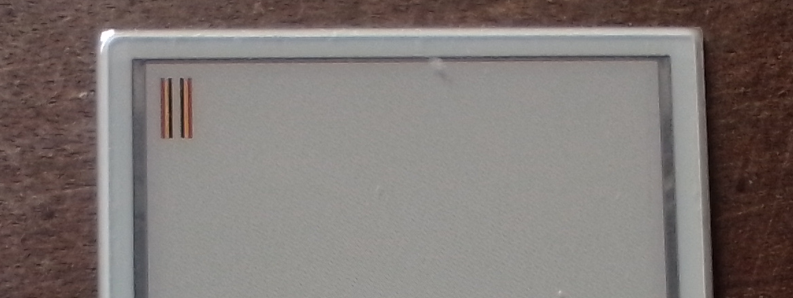
Image Processing
Alright, at this point we’ve taken a close look at how an image is represented and how its color information is encoded, but you’re probably wondering: How do I actually convert an image into the pixel data array I need for my application’s code?
To answer that, let’s walk through the entire process with an example.
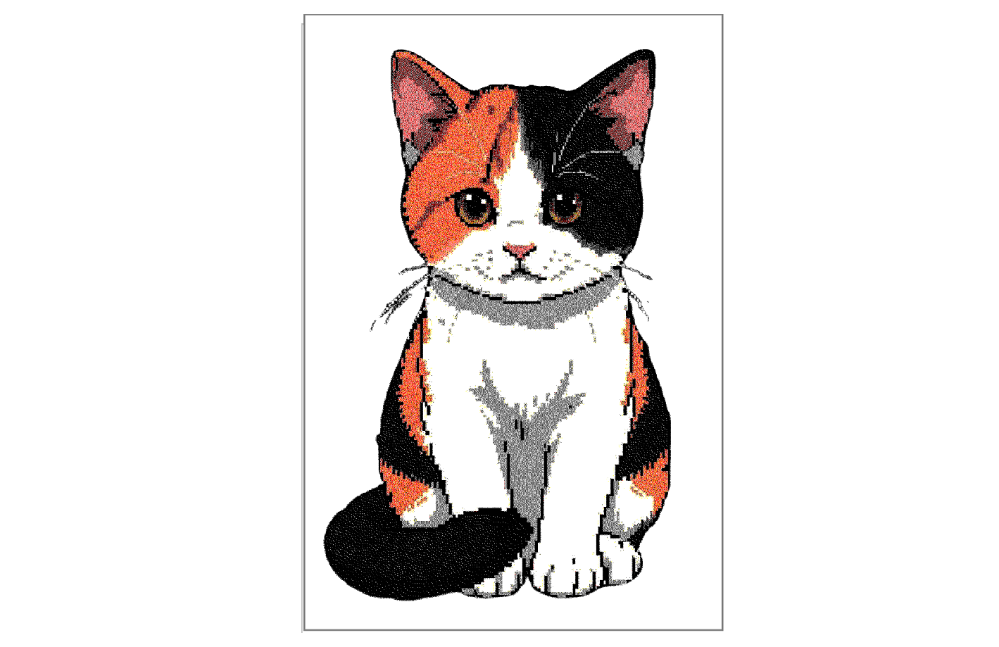
Imagine you want to display the following image on your 2.9-inch, 4-color EPD in vertical orientation:
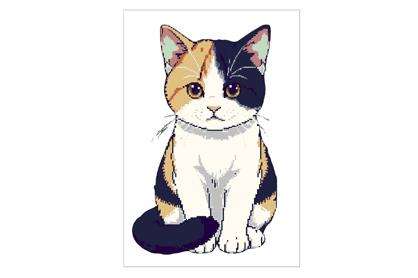
This image (shown here in reduced size) is originally 1024 pixels wide by 1536 pixels high, with 8 bits of color depth—that’s 256 different colors.
Obviously, as-is, it can’t be shown on the EPD: it’s way too big (much larger than 128 x 296 pixels) and has too many colors.
Step 1: Color Reduction (Quantization)
The first processing step is to reduce the number of colors.
We need to go from 256 colors down to just 4. This process is called color quantization, and you can do it with any image editor. In this case, I used GIMP and a custom palette that matches the 4 colors available on the EPD.
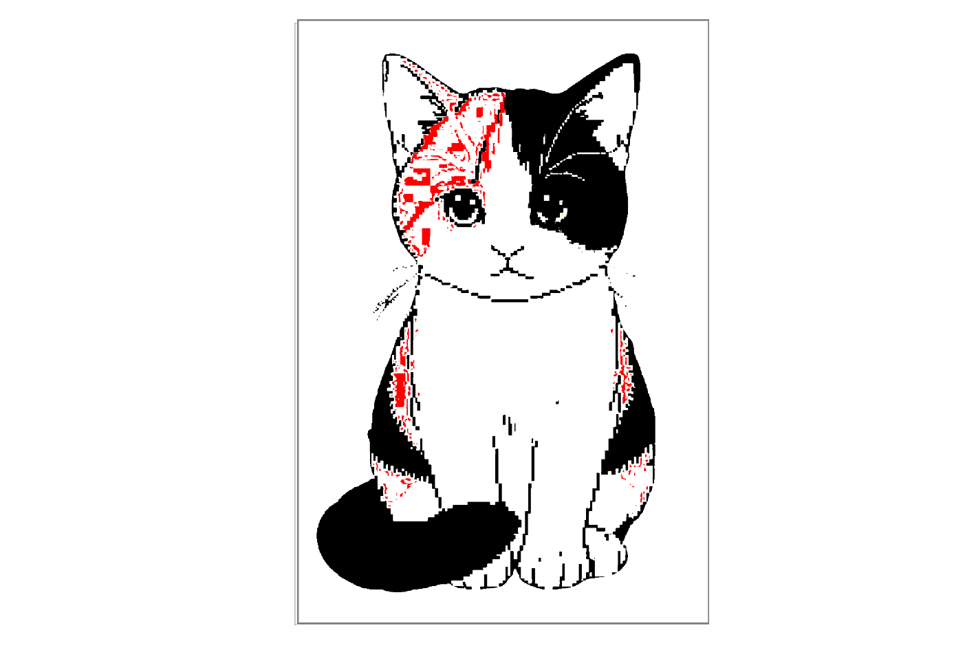
The result can look a bit disappointing—there’s a clear loss of quality.
The quantization algorithm picks the closest color in the new palette for each original pixel, and sometimes the difference is noticeable.
But don’t worry! There’s a trick you can try: dithering. Dithering “simulates” missing colors by mixing pixels of the available palette.
There are many dithering algorithms, and GIMP includes several. Here’s how the image looks using one called Floyd-Steinberg:
Much better, right? If you zoom in, you’ll notice some colors are made up of a combination of dots from the four base colors.
Step 2: Resize the Image
After reducing the number of colors, the next step is to resize the image to match the EPD’s pixel count—128 x 296. You can do this with almost any image editing software, like GIMP or even Windows Paint.

Now the image is ready. The final step is to convert it into a byte array using the format we discussed earlier.
Step 3: Convert to a Byte Array
For this last step, if you enjoy programming and are up for a challenge, you can build your own tool—either by experimenting with AI and a bit of vibe coding, or by writing your own script in Python using the Pillow library, which is great for image processing.
If you prefer something ready-to-use, Seeed Studio provides a fantastic online tool that does all of this in seconds. In fact, it can handle the full process: color quantization with dithering, resizing, and generating the array in the required format.
This tool is part of SenseCraft HMI, a free no-code solution for creating EPD applications: https://sensecraft.seeed.cc/hmi/tools/dither
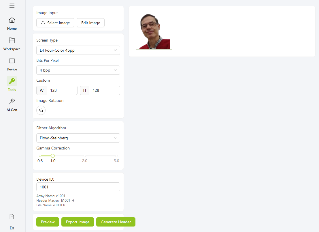
To continue with this example, I opened SenseCraft HMI, uploaded the original image, and configured the tool with the settings shown in the screenshot below:
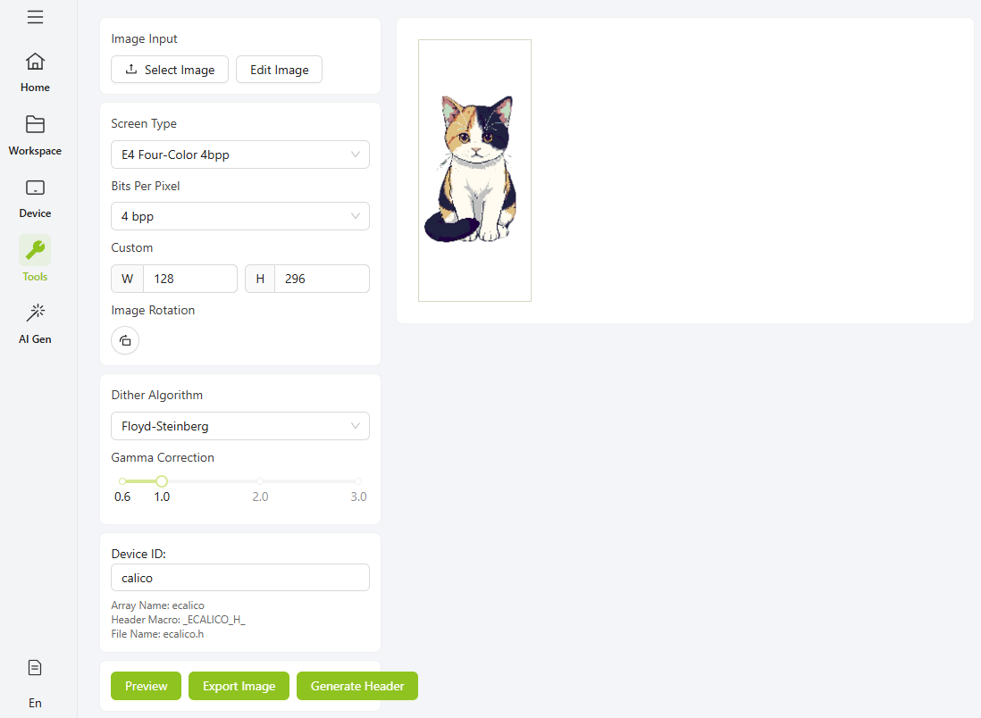
The selected display (Screen Type) is a four-color model, with a color depth of 4 bpp, and custom dimensions of 128 pixels wide by 296 pixels high. The chosen dithering method is Floyd-Steinberg, but you can experiment with any of the other available options.
Device ID is the name that will be used for the array containing the pixel data.
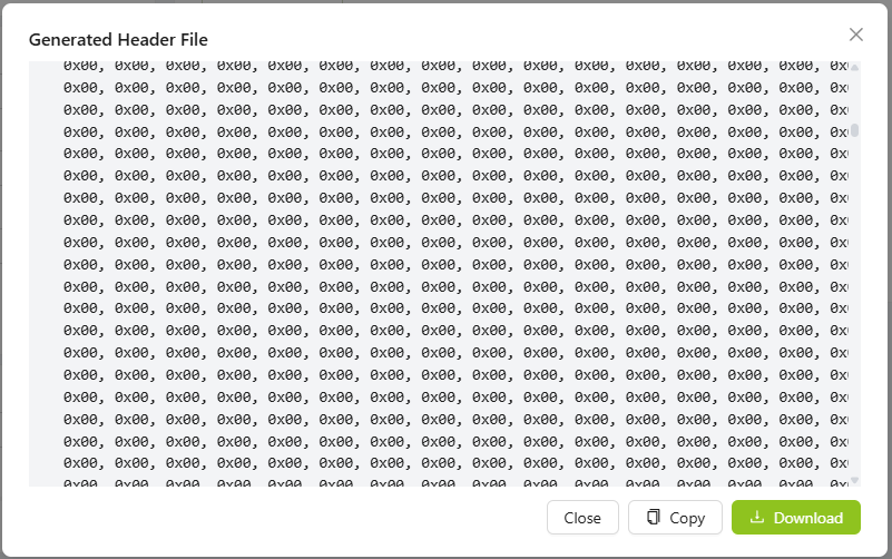
When you click the "Generate Header" button, the page creates a “.h” file with the array definition, which you can either copy to the clipboard or download.
Save that file in the same folder as your code and name it "image.h".
All that’s left to do is include that file in your code and call pushImage with the declared name of the array (the tool adds the letter “e” before the specified Device ID).
A complete code example to load and display the image would look like this:
#include "TFT_eSPI.h"
#include "image.h"

EPaper epaper;

void setup()
{
  epaper.begin();

  // Clear screen to white
  epaper.fillScreen(TFT_WHITE);

  // Display 4-color image
  epaper.pushImage(0, 0, 128, 296, (uint16_t *) ecalico);

  epaper.update();
}

void loop()
{
// Nothing to do here
}
And here is the final result:
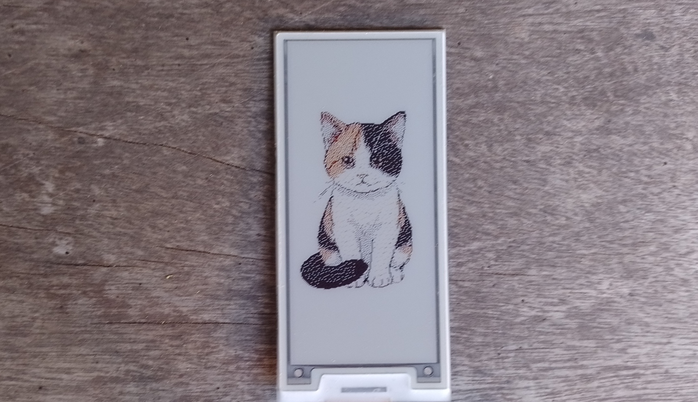
As you’ve seen, the original image went through several transformations that changed its appearance and quality quite a bit.
Whenever you want to display images using this process, you’ll probably need to experiment with different pictures or settings a few times until you get the result you’re looking for.
Conference Room Sign
Now that you know how to process images for EPD displays and are familiar with the available tools, let’s get back to the conference room sign project.
You’ll need an image of a person’s face (you can use your own or one generated by AI, but for this example, I’ll use mine since it was the easiest option for me), and process it as we’ve discussed, using SenseCraft HMI.
In my case, the image is 128 × 128 pixels, and I convert it to an array format using the following settings:
Once you have the array, you can use it to display the photo on one side of the screen. All that’s left is to add some text and read the button inputs.
However, there’s a small issue: as we saw in the badge project, the screen is in vertical orientation. If we try to write text, it won’t appear in the horizontal layout we want.
Fortunately, there’s a simple solution—rotate the screen.
Screen Rotation
When displaying images—and especially text—it’s important to make sure the content appears in the desired orientation. For this, Seeed_GFX includes a function that allows you to rotate the EPD screen.
Rotating the display involves several internal adjustments: it changes the origin of the coordinate system, swaps or recalculates the width and height values, and redefines how pixels are mapped in memory. The ePaper panel’s controller chip is capable of making these changes at the hardware level, which simplifies orientation management in your code.
The function used to perform rotation is setRotation, and the following image shows the results obtained when it is called with different values:
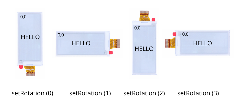
If you’re displaying images, be careful with the width and height dimensions.
In portrait mode (modes 0 and 2), the full screen dimensions are 128 × 296 pixels, while in landscape mode (modes 1 and 3), the image is interpreted as 296 × 128 pixels.
Button Reading
As we saw earlier when analyzing the features of the EE04 board, it includes four buttons: one RESET button and three others whose function is defined by the user.
Let’s now see how we can read these inputs and use them in our project.
In the following image, you can see a fragment of the EE04 schematic. As shown, the buttons are connected to GPIO2, GPIO3, and GPIO5 of the XIAO module.
These inputs have pull-up resistors, and pressing a button drives the signal to a LOW level.
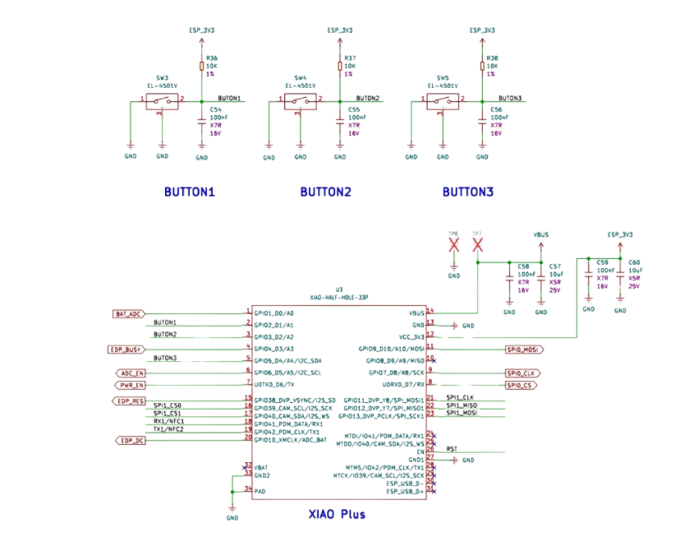
So all we need to do is configure those ESP32 GPIO pins as inputs and then monitor their state. When a pin reads LOW, it means the corresponding button has been pressed.
Here’s a simple example program that demonstrates how to read the buttons:
// Define pins
const int KEY1 = 2; // KEY0 - GPIO2
const int KEY2 = 3; // KEY1 - GPIO3
const int KEY3 = 5; // KEY2 - GPIO5

void setup() {
  // Initialize serial communication
  Serial.begin(115200);

  Serial.println("Press any key");

  // Configure pins as inputs
  pinMode(KEY1, INPUT_PULLUP);
  pinMode(KEY2, INPUT_PULLUP);
  pinMode(KEY3, INPUT_PULLUP);
}

void loop() {

if (!digitalRead(KEY1)) {
    Serial.println ("KEY1");
    delay (250);
  }


  if (!digitalRead(KEY2)) {
    Serial.println ("KEY2");
    delay (250);
  }


  if (!digitalRead(KEY3)) {
    Serial.println ("KEY3");
    delay (250);
  }
}
Final Code
Now let’s put all the pieces together to define the code for the conference room sign. Here’s the complete example you can use as a reference:
#include "TFT_eSPI.h"
#include "image.h"

// Define pins
const int KEY1 = 2; // KEY0 - GPIO2
const int KEY2 = 3; // KEY1 - GPIO3
const int KEY3 = 5; // KEY2 - GPIO5

// Define modes
const int SCHEDULED = 0;
const int ONGOING = 1;
const int FINISHED = 2;

int Mode = SCHEDULED;
bool ModeChanged = true;

EPaper epaper;

void setup()
{
  // Configure pins as inputs
  pinMode(KEY1, INPUT_PULLUP);
  pinMode(KEY2, INPUT_PULLUP);
  pinMode(KEY3, INPUT_PULLUP);


  // Initializes the screen
  epaper.begin();
  // Clear screen to white
  epaper.fillScreen(TFT_WHITE);
  // Settings
  epaper.setTextColor (TFT_BLACK);
  epaper.setTextSize (1);
  epaper.setRotation (3);

  // Display image
  epaper.pushImage(170, 0, 128, 128, (uint16_t *) e1001);

  // Titles
  epaper.setFreeFont (&FreeSansBold9pt7b);
  epaper.drawString ("EPD Technology",14,15);
  epaper.setFreeFont (&FreeSans9pt7b);
  epaper.drawString ("Prof. Tolocka",30,40);
  // Font for the Mode text
  epaper.setFreeFont (&FreeSansBold12pt7b);
}

void loop()
{ // Read the button inputs.
  // If any button is pressed, set the Mode value
  // and indicate that Mode has changed
  if (!digitalRead(KEY1)) {
    Mode = SCHEDULED;
    ModeChanged = true;
  }
  if (!digitalRead(KEY2)) {
    Mode = ONGOING;
    ModeChanged = true;
  }
  if (!digitalRead(KEY3)) {
    Mode = FINISHED;
    ModeChanged = true;
  }

  // If Mode changed, update the text
  if (ModeChanged) {
    // Clear the previous text
    epaper.fillRect (20,85,150,20,TFT_WHITE);

    switch (Mode) {

      case SCHEDULED:
        epaper.setTextColor(TFT_RED);
        epaper.drawString ("SCHEDULED",20,85);
        break;

      case ONGOING:
        epaper.setTextColor(TFT_RED);
        epaper.drawString ("ONGOING",20,85);
        break;

      case FINISHED:
        epaper.setTextColor(TFT_BLACK);
        epaper.drawString ("FINISHED",20,85);
        break;
    }
    ModeChanged = false;
    // Update the screen
    epaper.update ();
  }
}
At the top, the required header files are included, and the pins connected to the buttons are defined.
Next, constants are set for each of the possible modes or states the sign can indicate, along with the Mode variable, which tracks the current mode, and a ModeChanged flag that signals when the user has changed the mode by pressing a button.
// Define modes
const int SCHEDULED = 0;
const int ONGOING = 1;
const int FINISHED = 2;

int Mode = SCHEDULED;
bool ModeChanged = true;
This flag is set at the start so the sign will boot up in the SCHEDULED mode.
Next, the epaper object is created, the GPIO pins for the buttons are configured, and the display is initialized.
Using setRotate(3), the screen is set to landscape mode.
Then, the photo is loaded on the right side, and the conference title and speaker’s name are displayed. Of course, you can replace the photo and these texts with your own choices.
 // Display image
  epaper.pushImage(170, 0, 128, 128, (uint16_t *) e1001);

  // Titles
  epaper.setFreeFont (&FreeSansBold9pt7b);
  epaper.drawString ("EPD Technology",14,15);
  epaper.setFreeFont (&FreeSans9pt7b);
  epaper.drawString ("Prof. Tolocka",30,40);
In the loop, there are two main code blocks: the first one reads the buttons. If it detects that any button is pressed, it updates the value of Mode accordingly and sets the ModeChanged flag to signal the change. The second block displays the corresponding text for the current Mode, using different colors.
One thing to highlight is the following line, which clears the previous text before displaying a new one:
epaper.fillRect (20,85,150,20,TFT_WHITE);
Finally, after updating the text, the update() function is called to refresh the display.
The final result can be seen in the image below. The photo quality is quite acceptable, especially considering the display only supports only four colors.

Low Power Consumption
One of the main requirements for the room sign is low power consumption. To achieve this, it’s essential to take some precautions in the software to minimize energy use as much as possible.
Let’s break down the power consumption into two main parts:
- The EE04 board together with the built-in XIAO ESP32-S3 Plus.
- The EPD display.
For the ESP32-S3, there are several ways to put the microcontroller into low-power modes and wake it up with different events. This topic is well documented, so we won’t go into detail here.
As for the EPD’s power use, there’s an important point: the electrophoretic panel is bistable, meaning it doesn’t use energy while the image stays on the screen. However, the rest of the associated circuitry—like the controller chip—still draws power, and that’s what we need to manage.
The Seeed_GFX library offers two specific functions for this:
- sleep(), which puts the display controller into a low-power mode.
- wake(), which wakes it up when you need to update the image.
How these functions work depends on the specific panel driver. For example, on the JD79667 controller (used in the 2.9-inch, 4-color display), the sleep() function sends a special command to activate the chip’s low-power mode, while wake() performs a reset followed by a full reinitialization of the controller.
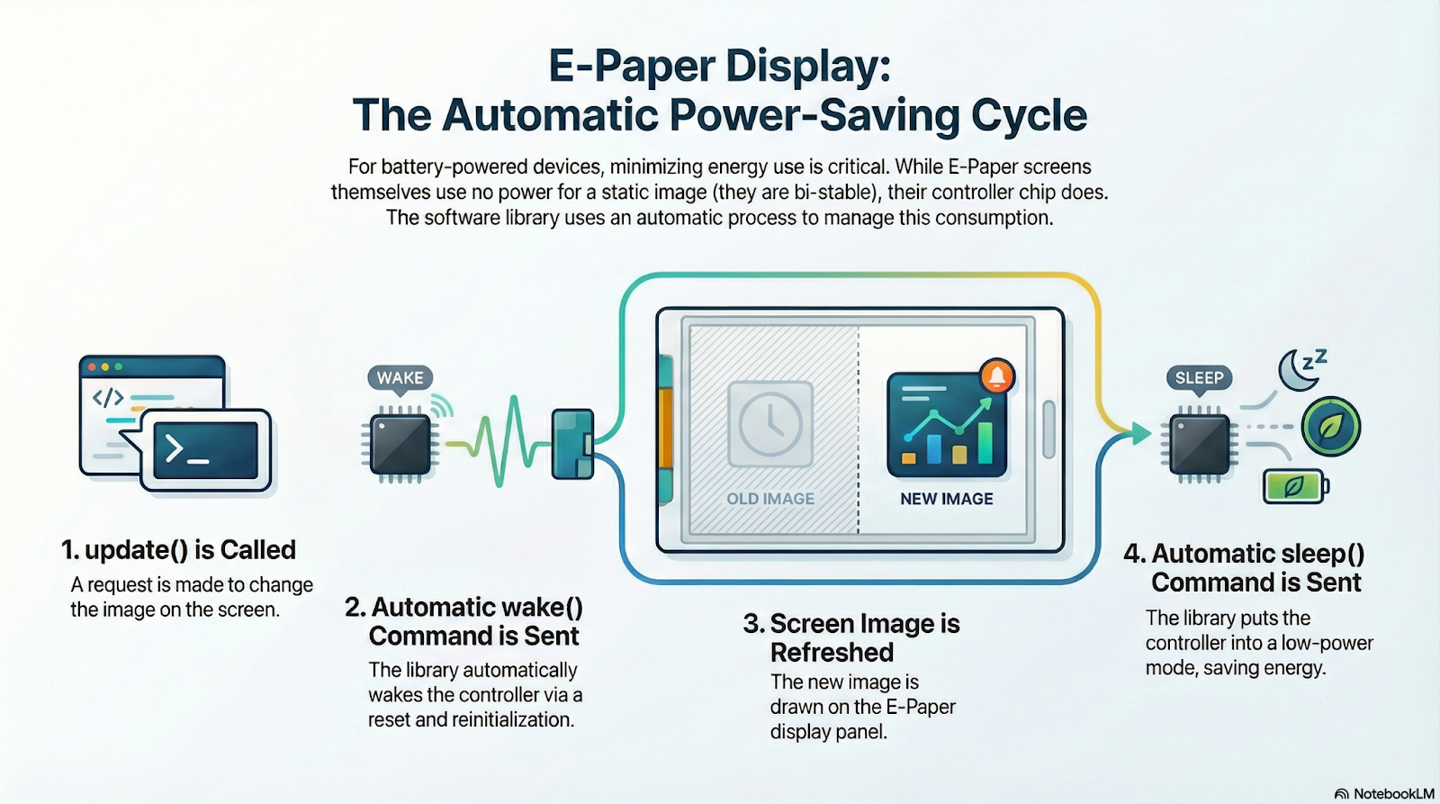
In practice, though, you hardly ever need to worry about managing this yourself, since the library handles it automatically.
Every time you call update(), Seeed_GFX internally calls wake(), updates the display, and once the process is finished, it calls sleep().
This mechanism ensures the display stays active for the shortest possible time, helping you achieve minimal power consumption.
Conclusions
Displaying color images with a certain level of quality, like photographs, is one of the most common applications for all kinds of electronic displays. The same applies to EPDs, although it’s important to be aware of their limitations. These screens don’t stand out for the number of colors they can show, but with some preprocessing—like color quantization and dithering—the reduction in color depth doesn’t impact the visual result as much.
In this project, we walked through the entire process of displaying images on an EPD: the necessary functions, the required preprocessing, how images are handled internally, and some useful tools for the job.
We also saw how to rotate the display for different orientations, how to combine images with text, and how to make use of the user buttons included on the EE04 board.
As I always say, this project is just an example and a reference guide—meant to inspire you as you implement your own ideas and projects.