IoT Mechanical Watch Winder
To solve the age-old first-world-problem of having too many automatic mechanical watches, configurable from a smartphone!
To solve the age-old first-world-problem of having too many automatic mechanical watches, configurable from a smartphone!
To make the experience fit your profile, pick a username and tell us what interests you.
We found and based on your interests.
iot_mww.zipCode of the Mechanical Watch Winder for the ESP8266 (Arduino based).Zip Archive - 8.63 kB - 01/29/2020 at 06:11 |
|
|
iotmww_schematics_rev2.0.pdfSchematics for the Mechanical Watch Winder electronics (rev 2.0).Adobe Portable Document Format - 110.97 kB - 01/29/2020 at 06:11 |
|
|
MWW_STL.zip3D printable STL files for the Mechanical Watch WinderZip Archive - 223.04 kB - 06/26/2019 at 15:40 |
|
|
After I saw that JLCPCB can manufacture 10 boards for $2 with a lead time of 2 days and express DHL shipping (I'm not actively promoting, just amazed and a bit concerned about their business model) I decided to design and order the electronics for the watch winder.
These are the boards:
Assembled it with some minor mistakes and temporary cables for power and programming:
Red cable is because I connected to the common pin of the darlington array to ground, it should've gone to 5V (short). The stepper didn't turn. Amazingly the thing just heated up, but didn't release its magic smoke. There's probably about $5-8 worth of electronics as of now.
The "motor driver" (darlington array) that came with the stepper motor was slightly too big for the PCB (16PDIP package), so I ordered some free samples from TI, I got 5 smaller versions (SO-16 package) of the ULN2003A which perfectly fit the available area.
The stepper motor connector was salvaged directly from the driver board it came with.
Since I had some space left I added a buzzer and broke out some pins just in case I wanted to add some features. I was expecting this to not be the first and only PCB for this project. I also added a large whited-out silkscreen area to write on (IP address, name, product code...) this will be gone too in the next version.
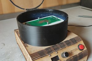
This is how the PCB will be mounted on the bottom of the winder:
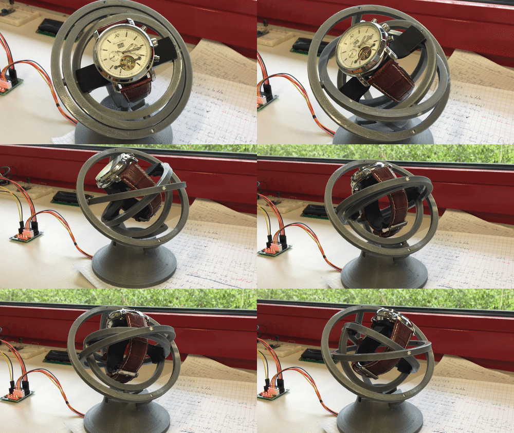
The Internet of Things Mechanical Watch Winder prototype winding one of my watches with me controlling it via a Node-Red interface:
The frame squeaks quite a lot, some parts need to be modified, it's incredibly annoying after a couple of minutes...
I designed this project using SolidWorks, it has some fun tools (non-intuitive as they can be sometimes...) like motion study. It allows to show how the device moves/performs when the motor turns, if the mating between the parts is done properly all connected elements follow the driving motor.
I added a rotational motor to the axis of the stepper motor and after fiddling with the settings for a while I got this mesmerizing moving mechanical watch winder:
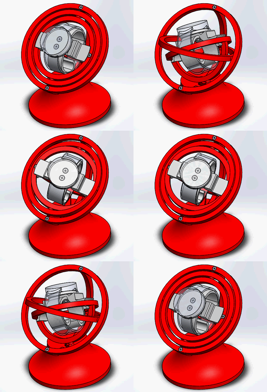
It turns out the side supports were unnecessary as the front and back supports for the big ring held it well enough.
Finally, instead of using pieces of filament and glue to connect the big ring to the supports and the small ring to the "inner support" I decided to use screws to avoid glue.
Regarding the hardware of the IoT mechanical watch winder it was important to me for it to run silently and be made with rapid prototyping tools such as a 3D printer. I found a design I really liked on which I decided to base my own version.
I ordered a stepper motor with a driver from eBay to see how loud it would be during runtime. The motor runs relatively silently depending on speed and commutation approach. The precision of the movement was not important.
I wanted to use an ESP8266-01 for the controller, however I discovered that it really lacks in GPIO. I was able to run the stepper motor (which needed 4 control pins) by sacrificing both GPIO and the serial TX/RX pins, but this required way too many external components (pull-up resistors) and made it awkward to troubleshoot. The ESP8266-12 had a lot more GPIO pins and was barely more expensive, so I decided to use it instead.
Create an account to leave a comment. Already have an account? Log In.
The web interface is based on Node-RED. You would need a server and an MQTT broker... it's really over engineered for the sake of it. The required circuit is dead simple: ESP8266, a linear regulator and a cheap servo driver, I added the schematics pdf file and the Arduino code to the supporting documentation for reference.
[this comment has been deleted]
Hi Isellens,
It slipped my mind a bit. I was in the process or porting it to Fusion 360 when life happened. I uploaded the STL files I had.
Cheers :)
WOOowww, this is great man, Do you mind sharing the files so I can make a similar design for my watch.
Congratulations on the work, could you share the files of this project?
Hey, amazing work, I love your project ! Is it possible that you share your solidworks files please? Thanks ! :)
Hey! Congratulations for your project! I'm doing the same project, maybe I can help! You can contact me Inbox! Thanks!
Hey, I'm not too sure on the winding mechanism, but what just curious. Are the full 3 axes of rotation required to properly wind the watch? Could it not be made to work on just a single pivot axis? I see you only use one motor but get an interesting (intentional) movement out of the mechanism.
Cool project regardless.
The 3 axes of rotation are not required of course, usually watch winders use only one axis of rotation, but I think this "gyroscope"-type design looks a bit more interesting.
Love your project! Do you have CAD files for the winder you made?
Yes, I used SolidWorks to design the parts. However, I am not quite happy with the base design, also I have no way to attach the electronics as I have not finished designing it (still waiting on the ESP8266-12).
Would you mind sharing the solidworks files you have? I think I would like to make a variant of the design
I will post the source files eventually of course, but currently it's work in progress.
Become a member to follow this project and never miss any updates
 Peter Wasilewski
 Vijay
Vijay
 Andy Geppert
 Jeroen Delcour
Great project.
I know this is an old project, but is it possible to get the schematics/wiring diagram and BOM for the electronics? I have a similar watch winder already printed and would like to be able to control it through a web interface.