 b.sverdlyuk
This is the second article dedicated to Lua programming for Lilka. The first article can be found here. When you start working with sensors, you almost immediately run into strange terms like High and Low. It might sound complicated, but in reality, it’s much simpler Just imagine a regular light switch: it’s either on or off. In electronics, that’s exactly what High and Low mean.
High means there is voltage on the pin — in other words, the signal is “on” ⚡ For a microcontroller, this is usually a logical one. Low, on the other hand, means there is no voltage (or it’s very low), which corresponds to a logical zero. So any simple sensor communicates with your device using this same language: either “yes” or “no.”
On Lilka, this feels especially intuitive. Press a button — you get High Release it — Low. A motion sensor detects movement — High again. Nothing happens — Low Even though these terms are rooted in electrical concepts, it’s enough at the beginning to think of them as just two states your device constantly switches between.
This simple idea is the foundation for most of the examples that follow. Once you get it, working with sensors stops feeling complicated and starts to feel more like building with a constructor set where everything is logical and predictable.
Relay Control on Lilka 🔌
This program turns a CW-020 relay on and off using button A on the Lilka console. A relay is an electrical switch that can control external devices: a light bulb, a fan, and so on ⚡. The module has a low level trigger — it activates when the INpin receives a low signal (~0V). That's why the program immediately sets HIGH on startup, so the relay doesn't accidentally switch on during boot. Button A toggles the relay, button B turns the relay off and exits the program. The screen shows the current state: green "State: ON" or red "State: OFF" 🟢🔴.
Wiring:
| Lilka | CW-020 relay |
|---|---|
| 3.3V | VCC |
| GND | GND |
| 12 | IN |
local relay_pin = 12
local relay_on = false

function lilka.init()
    gpio.set_mode(relay_pin, gpio.OUTPUT)
    gpio.write(relay_pin, gpio.HIGH)
end

function lilka.update(delta)
    local state = controller.get_state()

    if state.a.just_pressed then
        if relay_on then
            relay_on = false
            gpio.write(relay_pin, gpio.HIGH)
        else
            relay_on = true
            gpio.write(relay_pin, gpio.LOW)
        end
    end

    if state.b.just_pressed then
        gpio.write(relay_pin, gpio.HIGH)
        util.exit()
    end
end

function lilka.draw()
    display.fill_screen(display.color565(0, 0, 0))

    display.set_text_color(display.color565(255, 255, 255))
    display.set_cursor(10, 32)
    display.print("Relay control")

    if relay_on then
        display.set_text_color(display.color565(0, 200, 0))
    else
        display.set_text_color(display.color565(200, 0, 0))
    end
    display.set_cursor(10, 64)
    display.print(relay_on and "State: ON" or "State: OFF")

    display.set_text_color(display.color565(255, 255, 255))
    display.set_cursor(10, 100)
    display.print("A - toggle")
    display.set_cursor(10, 120)
    display.print("B - exit")
end
HC-SR04P Distance Sensor on Lilka 📡
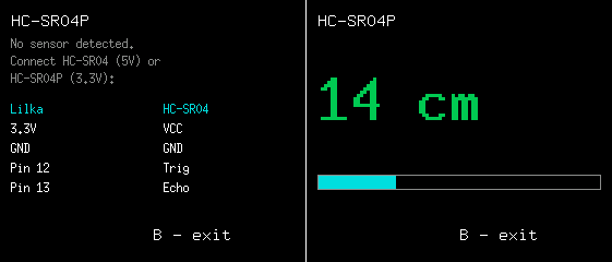
This program measures the distance to an object using the HC-SR04P ultrasonic sensor and displays the result in centimeters on the Lilka screen. The sensor works like a bat 🦇 — it sends an ultrasonic pulse and waits for the echo. The farther the object, the longer the sound travels. The program measures this time and converts it into centimeters.
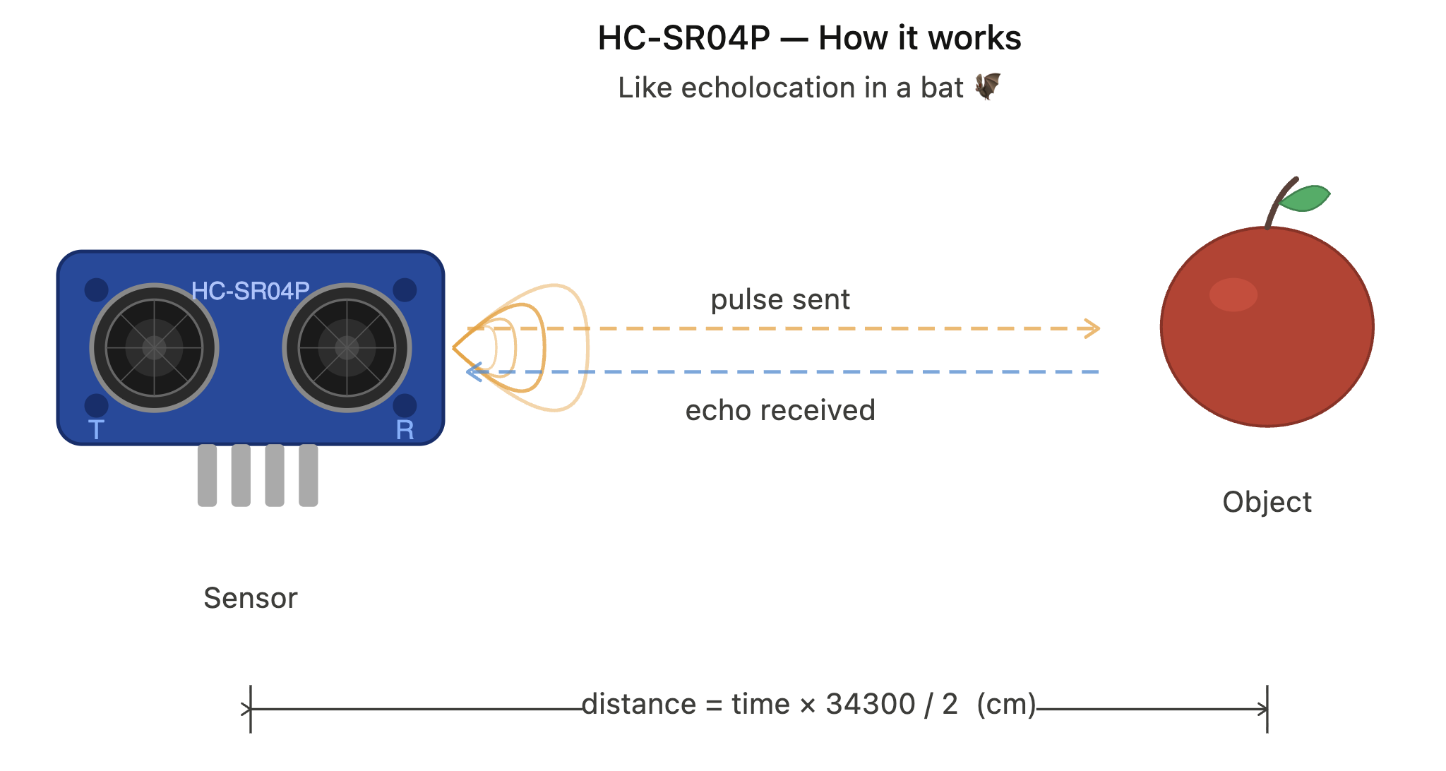
The key technical challenge — Lua has no built-in microsecond delay, but the sensor requires one. The solution is simple: util.sleep(0.001) gives a 1ms pulse — 100× more than the required 10µs minimum, and perfectly stable ⚙️. Readings are smooth thanks to averaging of eight measurements and an outlier filter — no sudden jumps to 800 cm 🚫. If the sensor is not connected, the screen shows a wiring guide. Button B to exit.
| Lilka | HC-SR04P |
|---|---|
| 3.3V | VCC |
| GND | GND |
| Pin 12 | Trig |
| Pin 13 | Echo |
local TRIG = 12
local ECHO = 13

local BLACK = display.color565(0,   0,   0)
local WHITE = display.color565(255, 255, 255)
local GREEN = display.color565(0,   200, 80)
local CYAN  = display.color565(0,   220, 220)
local GRAY  = display.color565(140, 140, 140)

local SMOOTH_N = 8
local MISS_MAX = 16   -- consecutive misses before showing wiring guide
local JUMP_MAX = 40   -- max allowed change per measurement (cm)

local samples    = {}
local miss_count = 0
local distance   = nil

local function measure()
    -- Send TRIG pulse: LOW -> HIGH -> LOW
    -- 1ms = 1000us, sensor needs minimum 10us, so 1ms is well within spec
    gpio.write(TRIG, gpio.LOW)
    util.sleep(0.001)
    gpio.write(TRIG, gpio.HIGH)
    util.sleep(0.001)
    gpio.write(TRIG, gpio.LOW)

    -- Wait for ECHO to go HIGH (start of echo pulse)
    local t = util.time()
    while gpio.read(ECHO) == 0 do
        if util.time() - t > 0.1 then return nil end
    end

    -- Measure how long ECHO stays HIGH
    local t_start = util.time()
    while gpio.read(ECHO) == 1 do
        if util.time() - t_start > 0.1 then return nil end
    end

    -- distance (cm) = duration (s) x speed of sound (cm/s) / 2
    return (util.time() - t_start) * 34300 / 2
end

function lilka.init()
    gpio.set_mode(TRIG, gpio.OUTPUT)
    gpio.set_mode(ECHO, gpio.INPUT)
    gpio.write(TRIG, gpio.LOW)
end

function lilka.update(delta)
    if controller.get_state().b.just_pressed then util.exit() end

    local result = measure()

    if result then
        miss_count = 0

        -- Outlier filter: if new value differs from current by more than
        -- JUMP_MAX cm — ignore it. Buffer stays unchanged, display is stable.
        if distance and math.abs(result - distance) > JUMP_MAX then
            return
        end

        table.insert(samples, result)
        if #samples > SMOOTH_N then table.remove(samples, 1) end
        local sum = 0
        for _, v in ipairs(samples) do sum = sum + v end
        distance = math.floor(sum / #samples)
    else
        miss_count = miss_count + 1
        if miss_count >= MISS_MAX then
            samples  = {}
            distance = nil
        end
    end
end

local function draw_bar(dist)
    if not dist then return end
    local W = display.width
    local bar = dist * (W - 20) / 50
    if bar > W - 20 then bar = W - 20 end
    display.fill_rect(10, 160, bar, 14, CYAN)
    display.draw_rect(10, 160, W - 20, 14, GRAY)
end

function lilka.draw()
    local W = display.width
    local H = display.height
    display.fill_screen(BLACK)

    display.set_font("9x15")
    display.set_text_color(WHITE)
    display.set_cursor(10, 24)
    display.print("HC-SR04P")

    if distance then
        display.set_font("10x20")
        display.set_text_size(3)
        display.set_text_color(GREEN)
        display.set_cursor(10, 110)
        display.print(distance .. " cm")
        display.set_text_size(1)
    else
        local R = W // 2 + 10  -- right column (sensor)
        local L = 10            -- left column (lilka)

        display.set_font("6x13")
        display.set_text_color(GRAY)
        display.set_cursor(10, 44)
        display.print("No sensor detected.")
        display.set_cursor(10, 60)
        display.print("Connect HC-SR04 (5V) or")
        display.set_cursor(10, 76)
        display.print("HC-SR04P (3.3V):")

        -- Column headers
        display.set_font("6x13")
        display.set_text_color(CYAN)
        display.set_cursor(L, 104)
        display.print("Lilka")
        display.set_cursor(R, 104)
        display.print("HC-SR04")

        -- Wiring rows
        display.set_text_color(WHITE)
        local rows = {
            {"3.3V",  "VCC"},
            {"GND",   "GND"},
            {"Pin 12","Trig"},
            {"Pin 13","Echo"},
        }
        for i, row in ipairs(rows) do
            local y = 104 + i * 18
            display.set_cursor(L, y)
            display.print(row[1])
            display.set_cursor(R, y)
            display.print(row[2])
        end
    end

    draw_bar(distance)

    display.set_font("9x15")
    display.set_text_color(WHITE)
    display.set_cursor(W // 2, H - 20)
    display.print("B - exit")
end
🚦Traffic Light App
This program works with a three-color traffic light module — a black board with three large LEDs: red, yellow, and green 🔴🟡🟢. Button A on Lilka turns the red LED on or off, button B controls the yellow one, button D controls the green one, and button C exits the program.
At the start the program declares three variables: led_pin_r = 21, led_pin_y = 47, led_pin_g = 48. These are convenient names for the pins on Lilka's expansion header where the module's signal wires are connected. Instead of writing the numbers 21, 47, and 48 everywhere, we give them readable names — r for red, y for yellow, g for green.
A pin is a physical contact on the Lilka board 🔌. Each pin can work in two modes: sending voltage outward (OUTPUT) or measuring voltage from outside (INPUT). The gpio.set_mode function selects the mode. The gpio.write function turns the voltage on or off. To use an analogy — gpio.set_mode is like hiring a worker and defining their role: a speaker (OUTPUT — sends a signal) or a listener (INPUT — receives a signal). And gpio.write is the specific command given to that worker: gpio.LOW means be silent (0 volts, LED off), gpio.HIGH means speak up (3.3 volts, LED on) ⚡.
That is why at the beginning of the program gpio.set_mode is called with gpio.OUTPUT for each pin — configuring it as an output. Then immediately gpio.write is called with gpio.LOW — turning the voltage off. This guarantees that all three LEDs are off when the program starts 👍.
After the setup the program enters an infinite while true do loop ♾️. Lilka constantly checks the button states in a circle — very fast, hundreds of times per second. Each time it calls controller.get_state() and checks whether a particular button is pressed.
The most interesting line is gpio.write(led_pin_r, 1 - gpio.read(led_pin_r)) 🧠. This is a simple math trick. gpio.read reads the current state of the pin and returns 1 if the LED is on, or 0 if it is off. Then 1 - 1 = 0 or 1 - 0 = 1. So if the LED was on — it turns off, if it was off — it turns on. One button controls both turning on and turning off at the same time.
Button C executes the break command which exits the loop and ends the program 👋. Without it the program would run forever.
led_pin_r = 21
led_pin_y = 47
led_pin_g = 48

gpio.set_mode(led_pin_r, gpio.OUTPUT)
gpio.write(led_pin_r, gpio.LOW)
gpio.set_mode(led_pin_y, gpio.OUTPUT)
gpio.write(led_pin_y, gpio.LOW)
gpio.set_mode(led_pin_g, gpio.OUTPUT)
gpio.write(led_pin_g, gpio.LOW)
while true do
    if controller.get_state().a.pressed then
        gpio.write(led_pin_r, 1 - gpio.read(led_pin_r))
    end
    if controller.get_state().b.pressed then
        gpio.write(led_pin_y, 1 - gpio.read(led_pin_y))
    end
    if controller.get_state().d.pressed then
        gpio.write(led_pin_g, 1 - gpio.read(led_pin_g))
    end
    if controller.get_state().c.pressed then
        break
    end
end
Simple Touch Sensor Button
This program is the simplest possible example of working with a touch sensor that behaves like a regular button. It continuously checks the state of a single pin connected to the sensor and simply displays the result on the Lilka screen.
When you touch the sensor, a signal appears on the pin — that’s the same as High. The program reads this value and understands that a touch has occurred, so it shows “TOUCHED” on the screen When you release it, the signal disappears (Low), and the screen displays “NOT TOUCHED”.
The logic here is as simple as it gets: there are only two states, constantly changing depending on whether you are touching the sensor or not. The program doesn’t store history, count presses, or add any complexity — it just “looks” at the pin right now and immediately shows the result.
This example clearly demonstrates the core idea of working with sensors: you read a value and react to it. It’s the first step toward more advanced projects, where instead of displaying text, you might control LEDs, servo motors, or even entire smart home systems.
touch_signal_pin = 12

gpio.set_mode(touch_signal_pin, gpio.INPUT)

function lilka.update()
    if controller.get_state().c.just_pressed then
        util.exit()
    end
end

function lilka.draw()
    display.fill_screen(display.color565(0, 0, 0))
    display.set_cursor(10, 32)
    local signal = gpio.read(touch_signal_pin)
    if signal == 1 then
        display.print("TOUCHED")
    else
        display.print("NOT TOUCHED")
    end
end
🌱 Soil Moisture Sensor
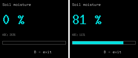
This program measures soil moisture using the Capacitive Soil Moisture Sensor v1.2 and displays the result as a percentage on the Lilka screen.
There are two common types of soil moisture sensors. Resistive sensors measure the resistance between two metal probes inserted into the soil — the more moisture, the lower the resistance. They are cheap but have a significant drawback: the metal probes rust in moist soil within just a few weeks 🦀. Capacitive sensors measure the dielectric permittivity of the soil without direct metal contact with moisture — so they last much longer and are a more reliable choice for permanent use.
The sensor connects to an analog pin on Lilka and returns a raw number from 0 to 4095 — this is the ADC value. The capacitive sensor has inverted logic: the lower the number, the more moisture is in the soil. The program converts this raw value into a percentage using a simple formula where DRY is the value in dry air (0%) and WET is the value in water (100%). Both the percentage and the raw ADC value are shown on the screen — useful for calibrating to your specific module 🔧.
Readings are smooth thanks to averaging of eight measurements — the number changes gradually without sudden jumps. On startup the program shows a wiring guide. Press A to start measuring. Button B to exit.
Pin 13 is used for analog reading. On ESP32-S3, the first 20 GPIO pins have a built-in ADC. Pins 12, 13 and 14 on Lilka's expansion header belong to this group — making them the natural choice for analog sensors.
Wiring 🔌
| Lilka | Sensor v1.2 |
|---|---|
| 3.3V | VCC |
| GND | GND |
| Pin 13 | AOUT |
-- Capacitive Soil Moisture Sensor v1.2
-- Wiring: VCC=3.3V, GND=GND, AOUT=pin 13
--
-- Typical calibration values for v1.2 at 3.3V:
-- DRY_AIR  ~3400 (sensor in open air)
-- WET      ~800  (sensor fully submerged in water)
-- Adjust these two constants if readings seem off.

local SENSOR_PIN = 13
local DRY        = 2634   -- ADC value in dry air = 0%
local WET        = 800    -- ADC value in water   = 100%

local BLACK = display.color565(0,   0,   0)
local WHITE = display.color565(255, 255, 255)
local CYAN  = display.color565(0,   220, 220)
local GRAY  = display.color565(140, 140, 140)

-- Smoothing: average of last SMOOTH_N readings
local SMOOTH_N = 8
local samples  = {}

local raw      = 0    -- latest raw ADC value
local moisture = 0    -- smoothed moisture percent (0-100)

local function read_moisture()
    local value = gpio.analog_read(SENSOR_PIN)

    -- Add to smoothing buffer
    table.insert(samples, value)
    if #samples > SMOOTH_N then table.remove(samples, 1) end

    -- Average the buffer
    local sum = 0
    for _, v in ipairs(samples) do sum = sum + v end
    local avg = sum / #samples

    raw = math.floor(avg)

    -- Map ADC value to 0-100%
    -- Sensor is inverted: lower ADC = more moisture
    local pct = (DRY - avg) * 100 / (DRY - WET)
    if pct < 0   then pct = 0   end
    if pct > 100 then pct = 100 end

    moisture = math.floor(pct)
end

local function draw_bar(pct)
    local W = display.width
    local bar = pct * (W - 20) / 100
    display.fill_rect(10, 170, bar, 14, CYAN)
    display.draw_rect(10, 170, W - 20, 14, GRAY)
end

function lilka.init()
    gpio.set_mode(SENSOR_PIN, gpio.INPUT)
end

function lilka.update(delta)
    if controller.get_state().b.just_pressed then util.exit() end
    read_moisture()
end

function lilka.draw()
    local W = display.width
    local H = display.height
    display.fill_screen(BLACK)

    -- Title
    display.set_font("9x15")
    display.set_text_color(WHITE)
    display.set_cursor(10, 24)
    display.print("Soil moisture")

    -- Large percent value
    display.set_font("10x20")
    display.set_text_size(3)
    display.set_text_color(CYAN)
    display.set_cursor(10, 100)
    display.print(moisture .. " %")
    display.set_text_size(1)

    -- Raw ADC value
    display.set_font("6x13")
    display.set_text_color(GRAY)
    display.set_cursor(10, 148)
    display.print("ADC: " .. raw)

    -- Bar
    draw_bar(moisture)

    -- Exit hint
    display.set_font("9x15")
    display.set_text_color(WHITE)
    display.set_cursor(W // 2, H - 20)
    display.print("B - exit")
end
Discussions
Become a Hackaday.io Member
Create an account to leave a comment. Already have an account? Log In.