 Pavel
PavelTo see, how it could look like, and to start using it already before permanent version is soldered, I made a prototype on breadboards -- it has 5 buttons and two 8-bit switch banks as inputs, as well as 4 7-segment displays wired for multiplexed use and 3,3,2 DAC for VGA output with RGB 332 color palette.
I did some testing with first primitive designs, and it seem to work ok.
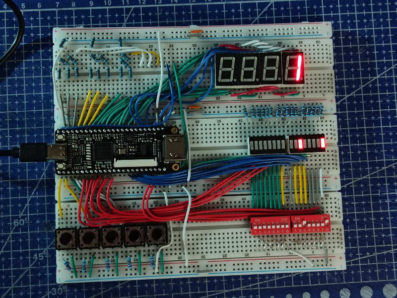 There are 8 1.8V IO pins, and all other IO is 3.3V logic. For my purposes 1.8V is too low voltage, and there seem to be little utility for these pins. The only thing I plan to interface this board with that has even lower working voltages is VGA interface. Thus these pins are to be used solely as outputs for VGA signal. On the prototype on photo they all connected to resistor network that forms 3 DACs (3, 3 and 2 bits, for R, G and B signals to be fed into VGA) in the top left corner.
All the other IO pins on the top side of the board are connected to 4 7-segment displays configured to be driven as multiplexed 4-digit display (similar to what I once did with discrete components).
On the bottom side there are 5 buttons connected, as well as 16 switches (for now 2 DIP switch banks). Switches are also paired with LED banks, so that there is correspondence between each switch an LED - one can see which switches are ON right away. These same pins connected to switches as inputs can be configured as outputs -- the LEDs will act as display; for them to work properly in this way, all switches should be in OFF state.
Discussions
Become a Hackaday.io Member
Create an account to leave a comment. Already have an account? Log In.