 Pavel
PavelThe Tang Nano 9k board has 8 outputs from 1.8V bank available on GPIO pins, which is somewhat odd, and not very useful for general purposes, as these signals could not be mixed directly with signals from other pins, which are all have 3.3V logic level. Thus I decided to use them as VGA output pins (VGA RGB needs voltages in the range between 0 and 0.7 V, so 1.8V outputs are ok for resistor ladder.
At first I thought to make the colors encoding as RGB 332, and use 2 other pins for sync signals, but after some deliberation chose RGB222 -- while now it is only 64 colors, this gives couple of grey shades in addition to black and white (the RGB332 does not have true greys among its 256 colors), and two pins that are left unused could be repurposed to output sync signals.
Here is a closeup on resistor ladders (R2R) and wiring before I placed the RGB connector sub-board on it:
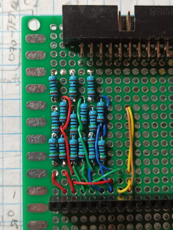
The wires are color coded -- ones carrying RGB signals are in their respective colors, and yellow wire carries hsync, while brown one is for vsync.
I used 150 Ohm resistors here, and wher I needed 75 Ohm, I wired a pair in parallel.
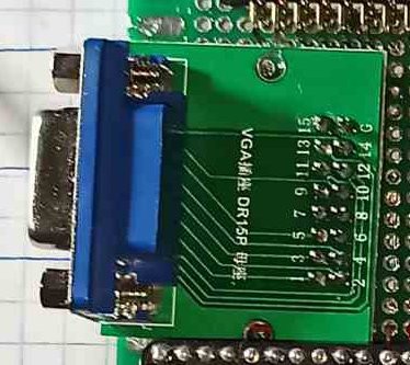
Afterwards I placed the connector on top and fixed it with epoxy to the main board:
------
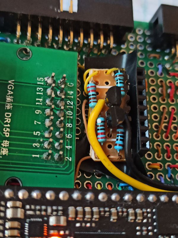
Well, the decision to use 1.8V pins for sync signals brought me some pain: I was sure that the sync signals can be same level as rgb inputs, i.e. 0.7V, and seeing elsewhere that they "tolerate" TTL inputs made me think that up to 5V can be applied, but 0.7V, or 1.8V as I had, would do. Instead it turned to be false, the 1.8V level is barely registered -- the monitor seem to seeing the sync, and sometimes flashed the test pattern for a moment, but most of the time remained dark. The solution turned to be a couple simple RTL inverter gates made from discrete 2n2222 transistor and couple of resistors, much the same as what I started with on the outset of my electronics hobby.
For their addition the sync wires should have been cut, and inverters had to be inserted between cut halves. As I was doing it after the board is complete, at the crowded place where components were held by epoxy, this was not quite easy. Luckily the sync wires weren't embedded in epoxy, and could be accessed, though with some work. The result is a small board attached as shown on the photo:
-----------
With the problem of sync signals logic levels solved, the test pattern was shown on display right away, and it was rock solid, with sharp edges, in contrast to what I saw when generating such signals with Arduino.
-----------
The VGA timings are calculated for 27 MHz pixel clock, so actual resolution is close to 686 by 480, with rectangular pixels that are slightly taller than their width, with overall picture aspect ratio 4:3, as for the proper VGA 640*480. The timings are correct and display monitor recognizes signal as standard.
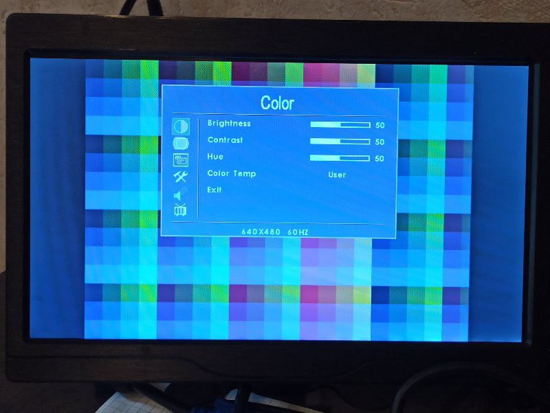
The test pattern is done just by feeding some bits from pixel counter to R and G channels, and from line counter to B channel, giving colored squares 32 by 32 pixels in size.
For deeper dive one can peruse verilog description of simple VGA controller used here.
-----
Here is what overall setup looked like:

Discussions
Become a Hackaday.io Member
Create an account to leave a comment. Already have an account? Log In.