 Pavel
PavelToday I finished primary soldering of all components on the board, and it looks like there is no bugs now.
The only thing I am planning to add here is one 74LVC245 chip in the spot under middle 20-pin connector, to be used as level shifter for 1.8V pins - to bring them up to 3.3V, thus on all 20-pin connectors all pins are 3.3V logic. But I do not have this chip yet, and haven't ordered it, so it will be deferred to future.
-----------------------
Here is how it looks like now,
front:
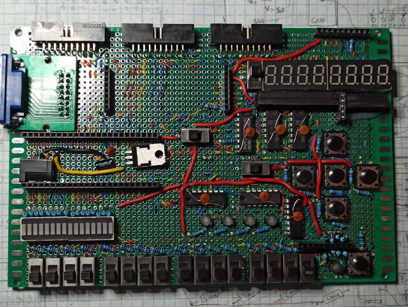
Going from top to bottom, left to right:
- The 3 20-pin connectors are on the top left and middle, they have all signal pins from Tang Nano 9k routed to them, as well as ground.
- Female pin header connector on the top right is the place for connecting small spi 128*64 graphical LCD.
- VGA connector on the right, obviously to connect to VGA display.
- pair of female pin header connectors placed vertically with empty space between them is the place for connecting spi 320*240 TFT color display.
- to the right is multiplexed 8-digit 7-segment display, with switch that turns it off.
- pair of long female pin header connectors on the left of middle row is the socket for inserting the Tang Nano 9k FPGA board. The switch to the right of it disconnects the rest of the board from Vcc.
- on the right side, 5 push-buttons are set in cross arrangement.
- on the bottom, 16 switches are placed, and over them are LED banks which indicate switch positions. These could also be used as linear display, one just have to make sure all switches are off.
-- between LED banks and buttons are 4 circular LEDs that could be used as additional display (though it is tricky, as they are multiplexed with buttons).
- in the bottom right corner of the board is yet another push-button, with circular LED that indicates when it pressed.
- over this LED + button combo is femal pin header connector with is the attachment point of the 16-button keyboard.
--------------
back:
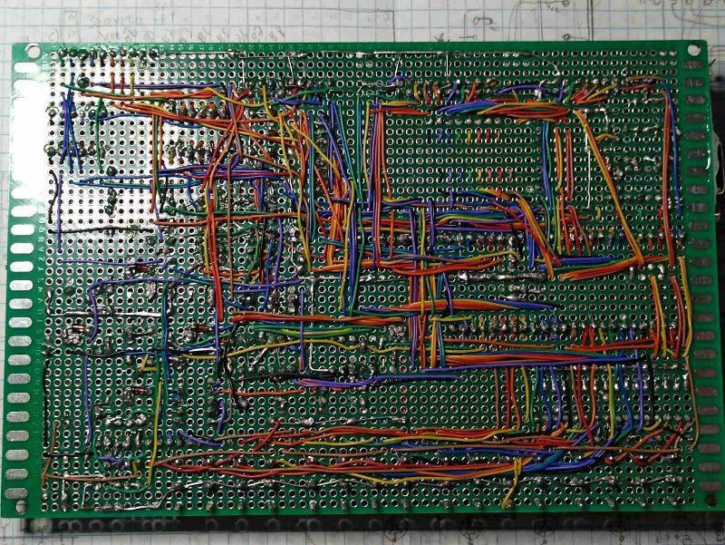 Most of the connections are routed on the back of the board by wire wrapping wire; the rest (mostly ground wires) are done by soldering component leads.
--------------------
Discussions
Become a Hackaday.io Member
Create an account to leave a comment. Already have an account? Log In.