ElectroScope Archive
Why Build a Robotic Arm?
Robotic arms mimic the kinematics of the human arm, offering repeatable control, high accuracy, and programmable motion. They’re used across:
-
Manufacturing: assembly lines, pick-and-place operations
-
Hazardous Environments: handling dangerous materials safely
-
Education & Research: hands-on learning for robotics concepts
-
Labs & Automation: pipetting, sample handling, repetitive tasks
This DIY build gives you a practical foundation in all of these areas with widely available components and open-source code.
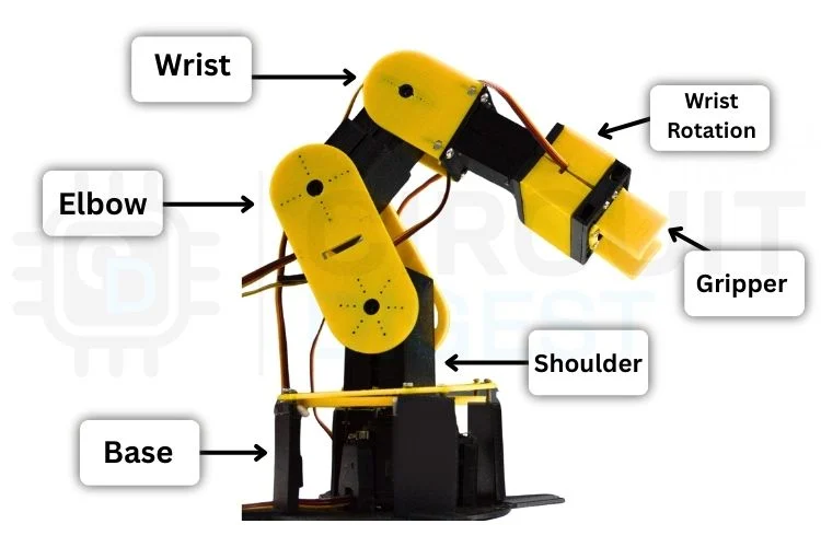
Core Components & Their Roles
| Component | Purpose |
|---|---|
| Arduino UNO | Main controller that runs servo motions and responds to control commands |
| Servo Motors (6x) | Each servo drives an axis from base to gripper |
| 3D-Printed Parts | Structural links, joints, and mounting points |
| Breadboard & Wires | Central hub for wiring and power distribution |
| External Power Supply | Provides stable current for all servos |
Proper design and calibration of these elements ensure smooth, reliable motion without overloads or jitter.

Understanding Robotic Arm Fundamentals
Before assembly, it's essential to grasp a few key robotics concepts:
Degrees of Freedom (DOF)
The number of independent movements the arm can perform; more DOF means greater flexibility and closer mimicry of human movement. A 6-DOF arm can perform complex, 3D motions.
Servo Motors
Hobby servos translate electrical PWM signals into precise angular motion. They are ideal for DIY robotics due to their ease of control and positional repeatability.
Power Supply & Control
Arduino cannot supply sufficient current for multiple servos — an external 5 V supply with adequate current capacity is required. Shared ground between Arduino and power supply is critical for stable signal reference.

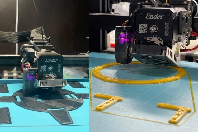
Mechanical Assembly & 3D Printing
All structural components — like the base, forearm, wrist, and gripper — are 3D-printed. Designing them in CAD ensures accurate fit and smooth movement. Assemble them using screws and ensure each servo is mounted securely to prevent vibration or unwanted torque.
Tips:
-
Ensure servo horns align to neutral (90°) before permanently fastening.
-
Use contrasting filament colors (e.g., yellow for moving parts, black for base) to visually differentiate sections.
Wiring & Circuit Execution
Connect each servo’s PWM wire to a dedicated PWM-capable Arduino pin. Use a common breadboard rail for the external power supply that feeds the servos, and make sure that Arduino GND is tied to the servo power GND. This shared ground maintains stable signal communication.
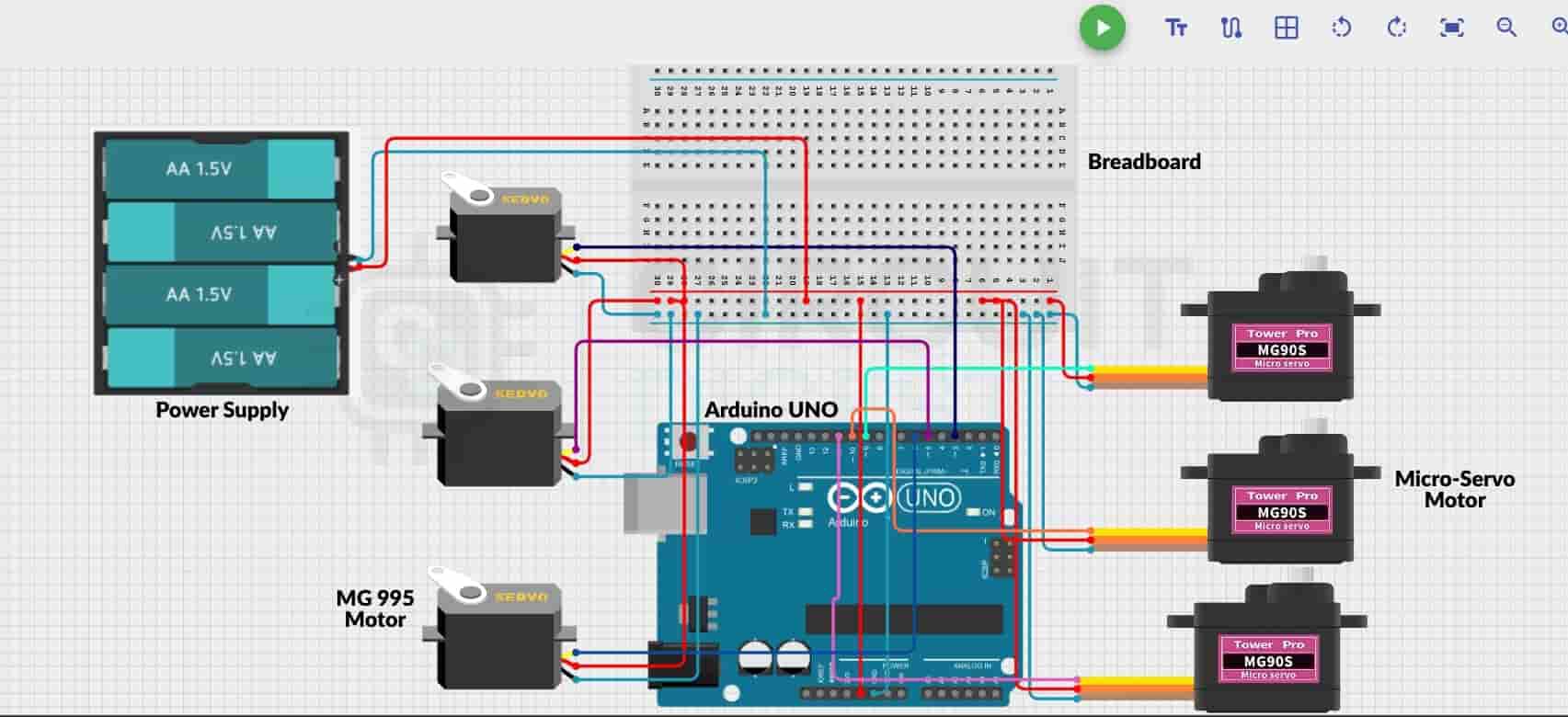
Programming & Smooth Motion Control
The Arduino sketch initializes all servos to a safe home position and listens for serial control commands. To achieve fluid motion, a custom function incrementally steps servos toward target angles, reducing vibration and electrical noise.
A simple snippet from the setup:
#include <Servo.h>
Servo base, shoulder, elbow, wristRot, wristPitch, gripper;
// ... attach servos and set initial positions ...
With this structure, your arm understands commands like B90 (base to 90°), and the motion logic ensures transitions are smooth and repeatable.
Web-Based Control Dashboard
One of the standout features of this build is the real-time control dashboard constructed with HTML, CSS, and JavaScript. Once loaded in a Chromium-based browser (e.g., Chrome), it connects to the Arduino via Web Serial API and presents:
-
Independent sliders for each joint
-
Reset & home position buttons
-
Record & Playback for motion sequences
-
Save/Load motion sequences as JSON files
This dashboard turns a browser into a powerful control station for your robot.

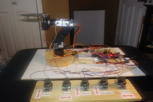
Operating Your Robotic Arm
-
Mount the assembled robot on a stable surface.
-
Connect servos to Arduino and power rails.
-
Upload the Arduino sketch.
-
Open the web dashboard in Chrome.
-
Move sliders to control joints and watch precise motion in real time.
Motion sequences...
Read more »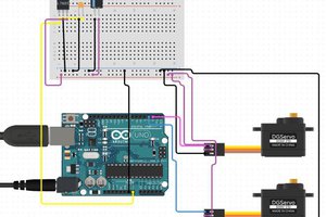
 hIOTron
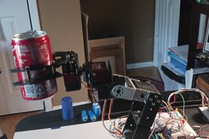
 G. Rosa
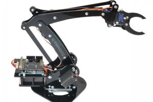
 Boris Landoni