 JP Gleyzes
Project Overview: 2S LiPo High-Current Power Box
This circuit is a high-performance power distribution system designed for large-scale RC models. It manages power from dual batteries to drive up to 16 High-Voltage (HV) servos while providing redundancy and electronic switching.
Key Technical Features
- Dual Battery Redundancy: The input stage features two "Ideal Diodes" (U$1, U$2). These allow for a dual-battery setup (2S LiPo, ~8.4V) with minimal voltage drop and prevent back-charging if one pack fails or has a lower voltage.
- High-Current Power Path: Utilizing multiple IRF4905 P-Channel MOSFETs in parallel, the board is designed to handle a continuous load of 20A, ensuring stable current delivery to 16 HV servos during high-torque maneuvers.
- Electronic Switching (Soft-Switch): * The circuit includes a logic stage (BSS123 N-FETs) that controls the main power MOSFETs.
- Compatibility: The "SW" header is designed to interface with Jeti RC switches or Magnetic switches. It uses a "fail-on" logic where the system remains powered if the switch signal is lost, enhancing safety.
- Servo Distribution: The output rail (VSERV) distributes power across 20 headers (JP1-JP20), supporting 16 primary servos with integrated decoupling capacitors (C1, C2, C3) to filter voltage spikes and electrical noise.. (Note that servos 1, 2, 3, 4, 13, 14, 15 and 16 have dual connectors, while 5 to 12 have single connectors)
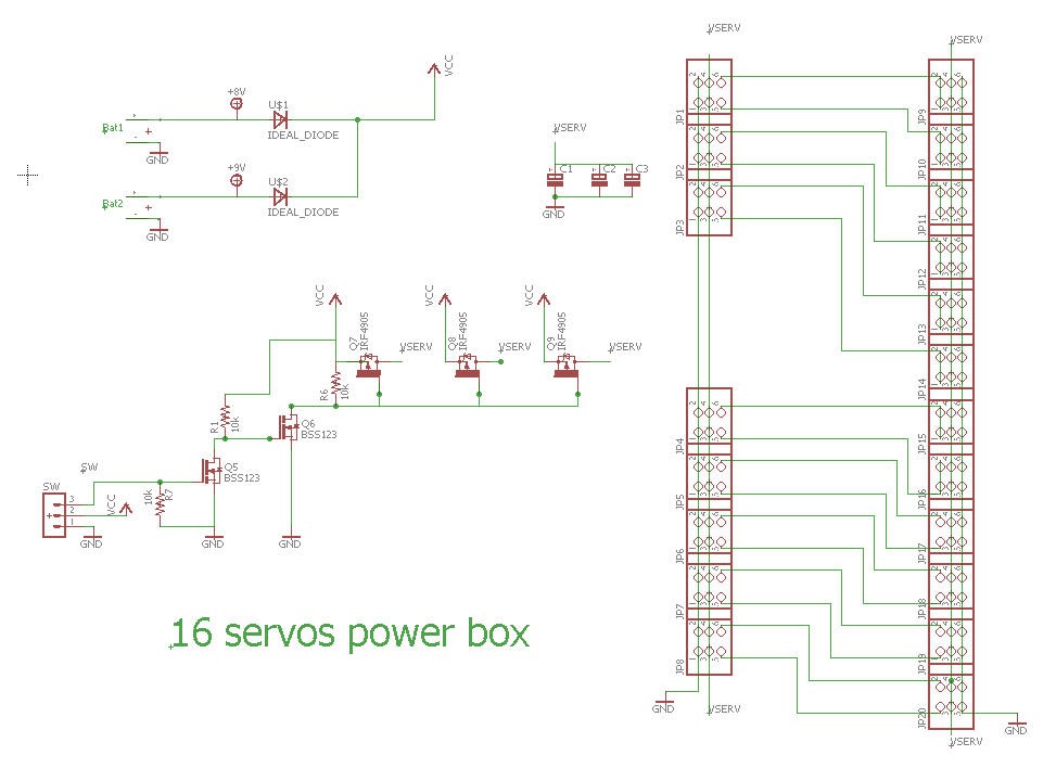
Schematics
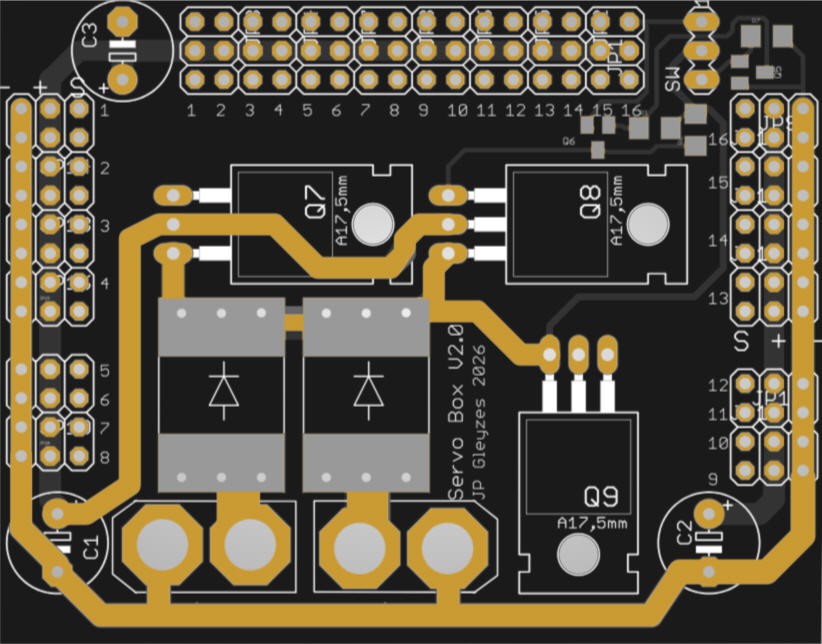
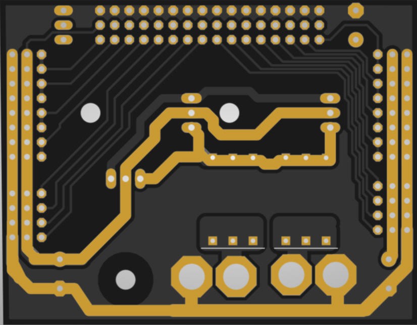
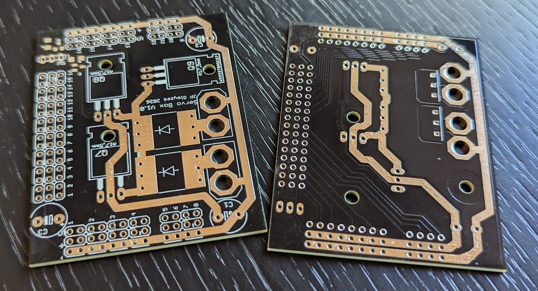
PCB
The PCB can be bought at PCBWay
The PCB was kindly sponsored by PCBWay and is as usual of excellent quality.

You can order it here :PCBWay shared project. It's cheap, delivered very fast and so professional looking!
and if you are new to PCBWay please use this affiliated link : https://pcbway.com/g/o35z4O
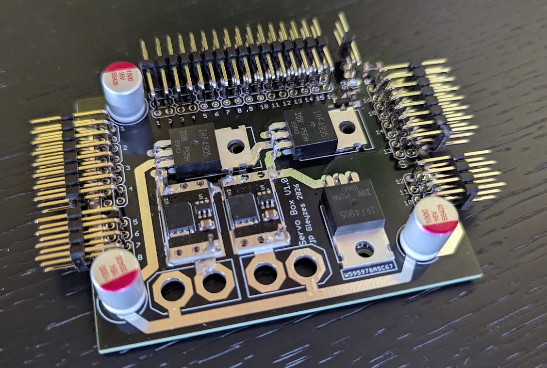
As you can see "big" tracks are exposed to be reinforced either with solder or (better) with copper wire. Doing this will increase drastically the current capcabilities of this board. It will sustain up to 20A with a total of 16 servos powered with 2s lipo packs.
Power considerations
2x 2s lipo packs are used to power the box. The "OR" of their voltage is performed with two ideal diodes
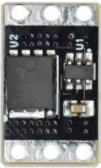
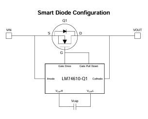
These tiny devices are available for cheap on Aliexpress. They are mostly used as "anti back flow" components on solar panels. The XL 74610 is an ideal diode module built around the brilliant LM 74610 chip from Texas Instruments.
When paired with an N-channel power MOSFET, it behaves like a diode, but with a significantly lower voltage drop.
Switch control
A three stages mosfet combination allows to switch On/Off the power box
The three big P channels mosfets IRF4905 are used to cut the VCC line.
Each Mosfet can handle 74A
Heat Dissipation per MOSFET
- Current Split: Assuming the load is balanced, each MOSFET carries approximately 6.67A
- The IRF4905 has a typical resistance of 0.02Ω at VGS = -10V$.
- Power Dissipation per Component: P = 0.02 * (6.67)^2 = 0.89W
Thermal Analysis
- Total Power Box Dissipation: Approximately 2.67W of total heat across the power stage
This means that the mosfets should remain totally cold and no heatsink willbe needed.
Reliability : 3 mosfets are soldered in parallel allowing a very strong reliability in case of one or even two Mosfets failure.
Switching Logic and Fail-safe Mechanism
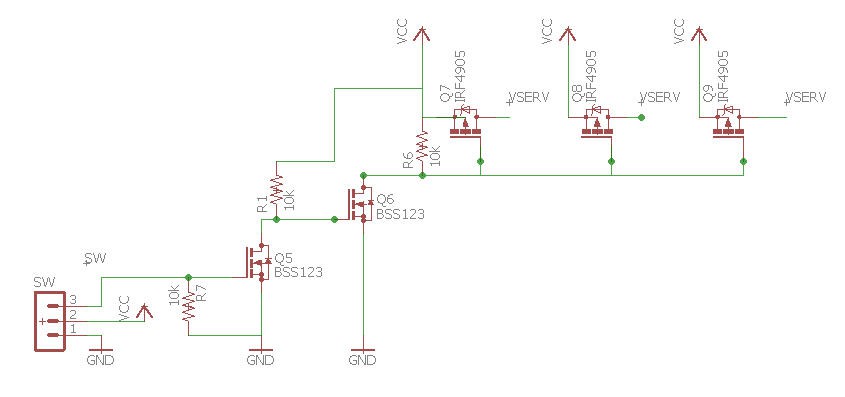
The switch circuit uses a dual-stage N-FET inverter logic to control the main high-power P-MOSFETs (Q7, Q8, Q9).
Operating States
- Off State (Switch Closed): When the switch pulls pin 3 of the SW header to GND, Q5 is turned off. This allows the gate of Q6 to be pulled High, turning Q6 ON. Q6 then pulls the gates of the IRF4905s to GND, which turns the main power ON.
- On State (Switch Open): Inversely, when pin 3 is High (3.3V or 5V), Q5 turns ON, pulling Q6's gate to GND and turning Q6 OFF. The 10k resistor (R6) then pulls the IRF4905 gates to VCC, turning the main power OFF.
Fail-safe Logic
This design features a "Fail-On" safety mechanism, which is standard for high-end RC power systems:
- Mechanical Failure: If the external switch fails, its wires are cut, or it becomes unplugged, the gate of Q5 is pulled to GND by the 10k pull-down resistor (R7).
- Result: Q5 remains OFF, Q6 remains ON, The IRF4905s stay ON.
- Safety Benefit: If the switch fails during flight, the power to your receiver and servos is maintained, preventing a crash.
Box for the power box
An enclosure for the PCB can be 3D printed? It will accomodate the PCB soldered with 90° pin headers, so that its form factor should remain "flat" when inserted into the plane.
If you prefer vertical pin headers, you will have to redesign the box (which is not complex !)
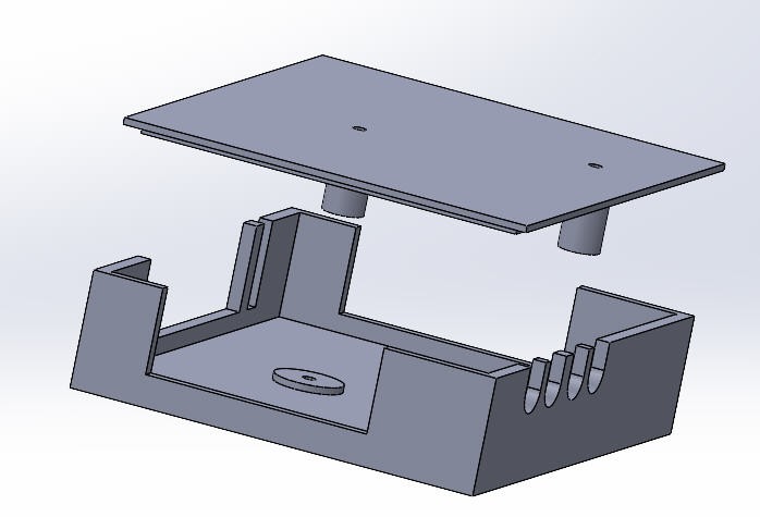
Parts are available on thingiverse : https://www.thingiverse.com/thing:7291279