How It Works
The system is split into two main parts:
1. Image Capture + SSTV Transmission (ESP32-CAM)
The ESP32-CAM captures a snapshot and converts it into an SSTV signal (Martin M1 format).
This audio signal is then sent directly into a cassette recorder.
The original SSTV generation code was inspired by the great work of Desafioinventor, from this project:
https://www.instructables.com/SSTV-Capsule-V2-for-High-Altitude-Balloons/
I adapted and modified it to fit this camera + tape workflow.
2. Tape Playback + SSTV Decoding (RP2040)
When the cassette is played back, the audio is routed into a Raspberry Pi Pico (RP2040) which decodes the SSTV signal and reconstructs the image.
The decoder was originally based on the excellent SSTV decoder by Jon Dawson:
https://101-things.readthedocs.io/en/latest/sstv_decoder.html
But cassette tape playback introduces a major challenge:
Tape speed is never perfectly stable ( and even worse with a cheap tape deck ), This causes frequency drift and sync dropouts.
So a large part of this project was improving robustness:
- Stronger filtering for noisy tape audio
- Reduced decoder lock loss
- Better sync recovery despite wow & flutter
- Limiting false detections
- Improved stability for imperfect analog playback
It’s far from perfect, and a lot was done with vibe coding, but it’s better and I don’t need to replace the Tape Deck with a higher quality one for now.
Extra Feature: Serial Image Recovery
A bonus addition is the ability to export the decoded image directly over USB serial.
A small PC program on Processing can capture the reconstructed frame, making it easy to save images digitally after decoding on the computer.
Hardware Used
ESP32-CAM (image capture + SSTV encoding)
Raspberry Pi Pico / RP2040 (SSTV decoding)
2.8" TFT display ILI9341 (view decoded image) ( https://www.aliexpress.com/item/4000219159401.html )
Audio cassette deck module ( https://www.aliexpress.com/item/1005009741792396.html )
Speaker + one transistor audio amplifier
DC/DC Converter 3.3V and 5V ( https://www.aliexpress.com/item/1005006486956558.html )
MOSFET module for motor control ( https://www.aliexpress.com/item/1005010280725977.html )
UPS Lithium Battery Module ( https://www.aliexpress.com/item/1005008696539803.html )
Custom 3D printed enclosure
Schematic:
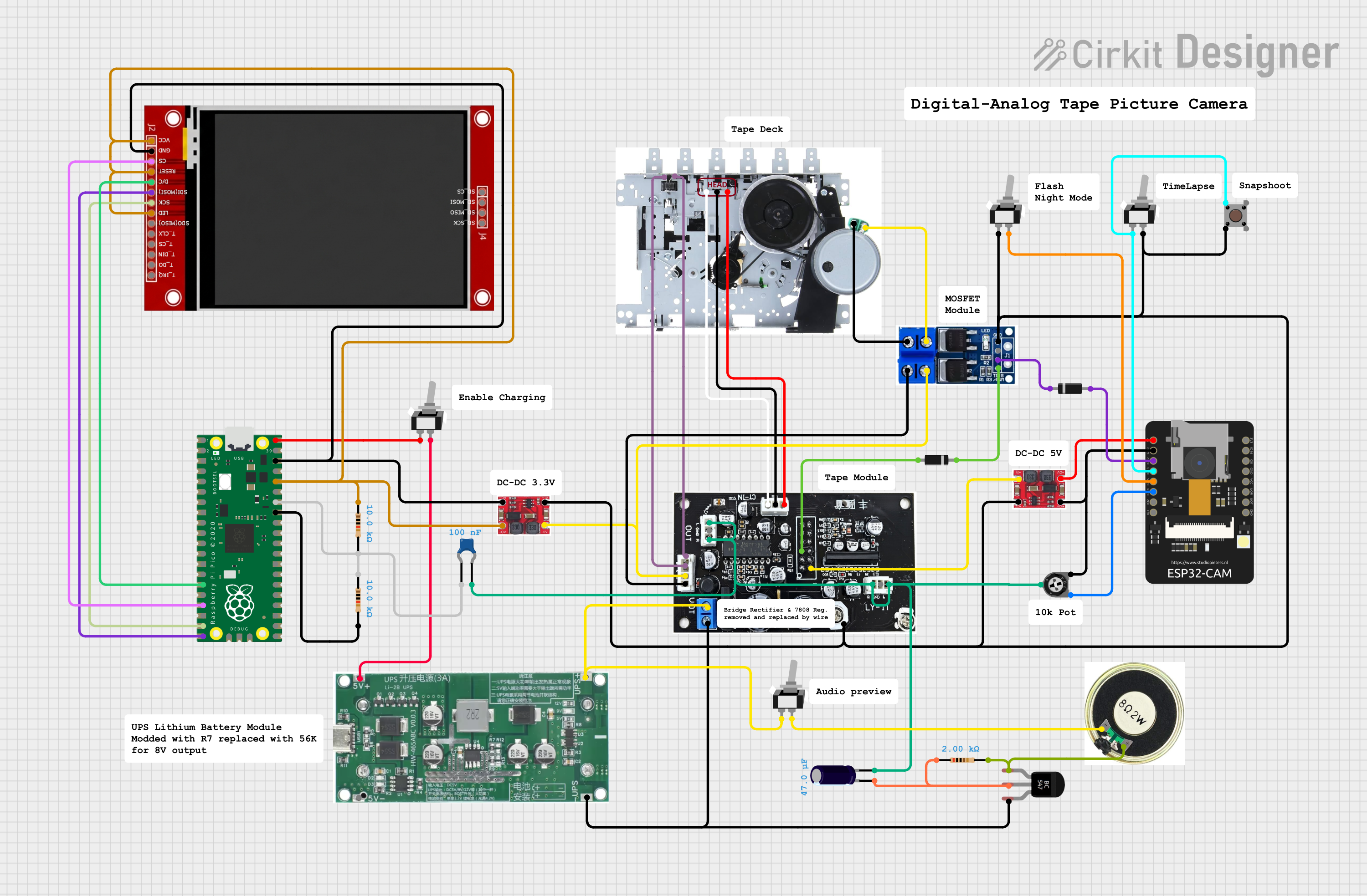
Physical Controls & Camera Modes:
To make the device feel like a real standalone camera, several hardware switches were added close to the front panel.
Flash / Night Mode Switch
This switch enables the LED flash and adjusts some camera settings for low-light conditions.
Time-Lapse Mode Switch
This switch activates an automatic time-lapse recording mode.
When enabled, the camera repeatedly captures images continuously and records them sequentially onto tape as SSTV frames.
Snapshot Button
A dedicated push button triggers an instant capture
Audio Preview Switch
This switch enables direct monitoring of the SSTV audio output through a small speaker.
It allows you to hear the signal live.
Charging Enable Switch
This activates the charging from the USB of the RPico, it gives the possibility to disable it during image recovery via the USB because the charging causes audio noise and reduces the quality of the recovered images.
Small test video:
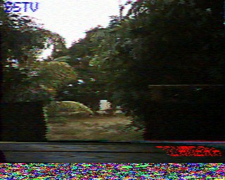
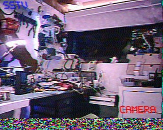
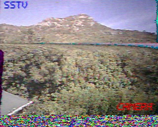
Some recovered pictures: