 Arnov Sharma
The goal of this project was simple: I’m planning to attend an upcoming Comic Con event in Gurugram, and I wanted to create a quick, wearable gauntlet-style prop. I won’t be wearing the full suit—just the gauntlet—and the Mega Buster is something I’ve always wanted to build. I used to play Mega Man X on my Windows 98 PC years ago. The game was brutally hard, but it was a big part of my childhood, and I wanted to bring a piece of that nostalgia into the real world. That’s why I chose the Mega Buster.
Here's how it works: inside the Mega Buster, there’s a push button used to trigger the firing sequence. When the button is pressed and held, the blaster begins charging and plays a charging sound effect. Once the button is released, the front red LED flickers, simulating the firing of a plasma beam.
The plasma beam remains active for the duration of the button press; the longer the button is held, the longer the beam fires. After firing, the effect slowly fades out and turns off.
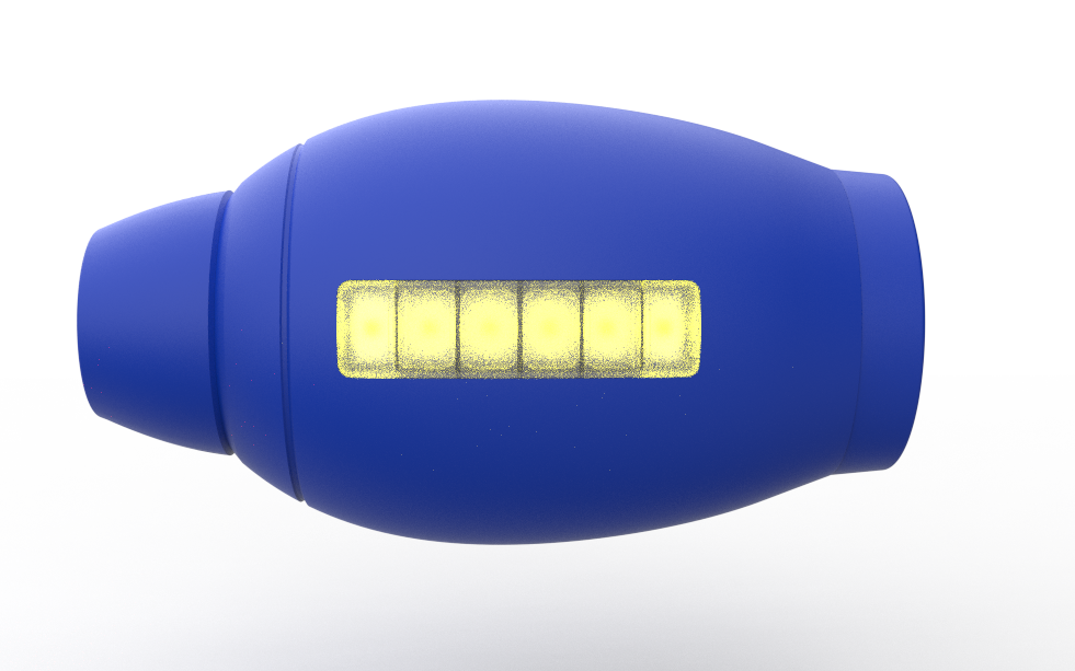
On the side of the blaster, there’s a six-bar power indicator that acts like an ammo meter. Each time the plasma beam is fired, one bar is depleted. Once all six bars are empty, the side indicator, front blaster LED, and speaker all blink red for 10 seconds, indicating a cooldown period. After the cooldown finishes, the device resets and power is fully restored.
This article covers the complete build process of the project from design to electronics and final assembly.
Let’s get started.
MEGAMAN
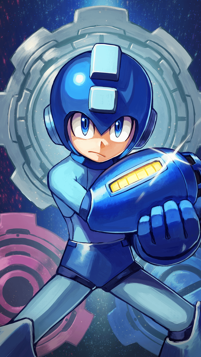
For anyone unfamiliar, Mega Man, also known as Rockman in Japan, is a classic action-platformer franchise created by Capcom. The series follows a humanoid robot named Mega Man, originally called Rock, who battles rogue robots using special weapons acquired from defeated enemies. One of the most iconic elements of the franchise is the Mega Buster, an arm-mounted energy cannon capable of firing charged energy shots.
Since its debut in the late 1980s, the Mega Man franchise has become known for its tight controls, memorable music, and challenging gameplay, earning a dedicated fan base across multiple generations.
My introduction to the Mega Man universe came through Mega Man X. Unlike the original Mega Man series, Mega Man X does not focus on the original Mega Man (Rock). Instead, the main protagonist is X, a new-generation robot created by Dr. Light. X is designed with the ability to think, feel, and make moral decisions, which gives the Mega Man X series a darker and more mature tone compared to the classic games.
Another major difference introduced in the Mega Man X series is Zero. Zero is a powerful ally and sometimes rival who uses a beam saber instead of an arm cannon. While early Mega Man X games focus mainly on X, later titles allow players to switch between X and Zero, each offering distinct fighting styles, abilities, and upgrades.
Now that the basics are covered, let’s move on to the project.
https://megaman.fandom.com/wiki/Mega_Man_Knowledge_Base
DESIGN

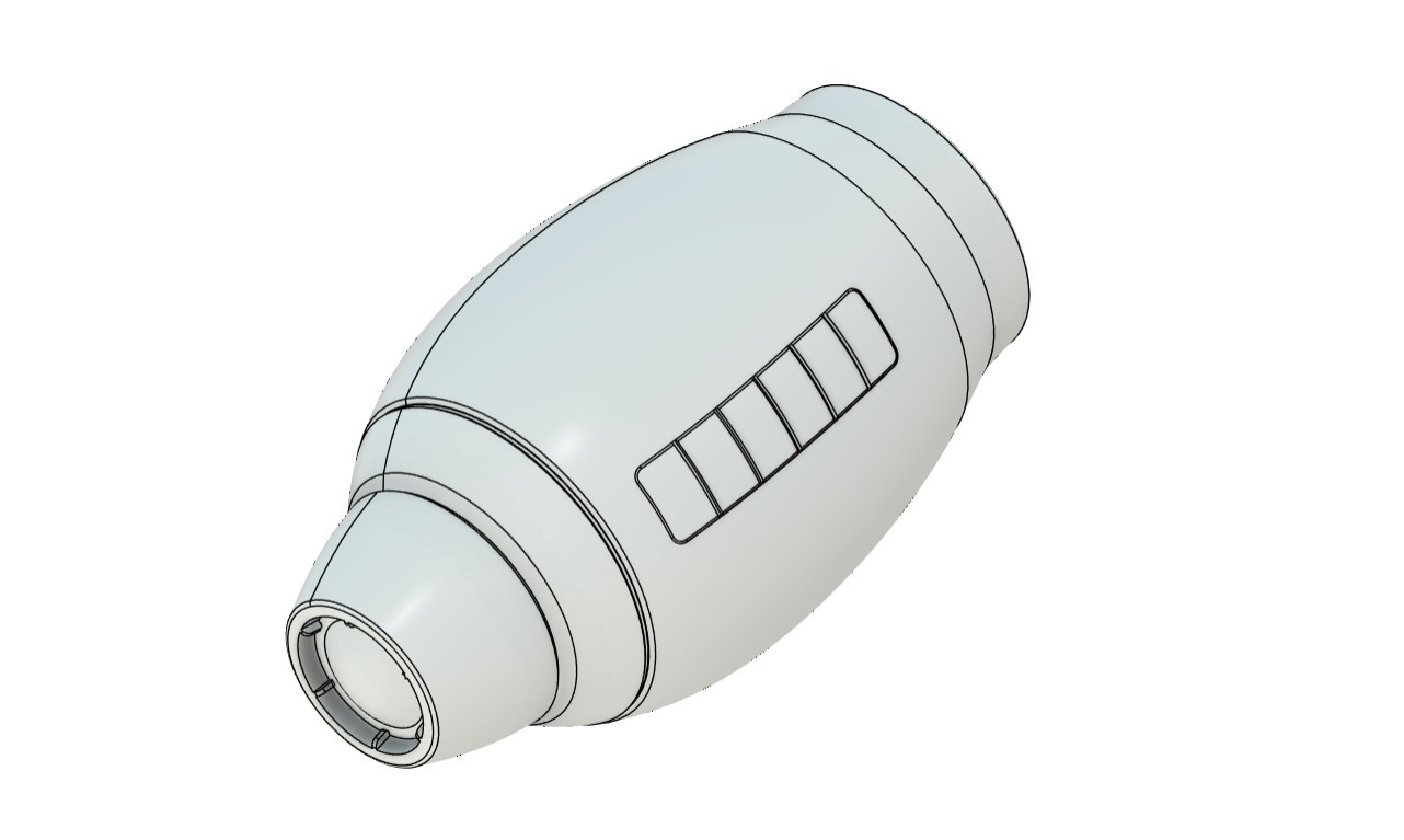


We start the 3D model-making process by first getting a reference image of the Rock Buster from the internet. We import the image into Fusion 360 through the canvas option, then use the calibration function to set the length of the whole gauntlet to 330 mm.
The whole gauntlet is symmetrical, so we can easily make this using the revolve function. To do this, we trace the outline of the gauntlet and then use the revolve function to make a solid gauntlet body.
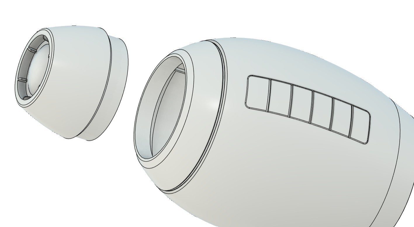
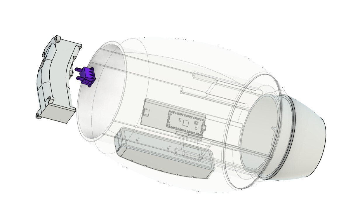
For the engineering process, we first divide the body into three main sections. The front part is the blaster section, the middle body is a hollow part in which we add the handle grip that is used to hold the whole gauntlet, and inside this section we also add the main control circuit. The third part is the back section, which contains a cushion that supports our arm.
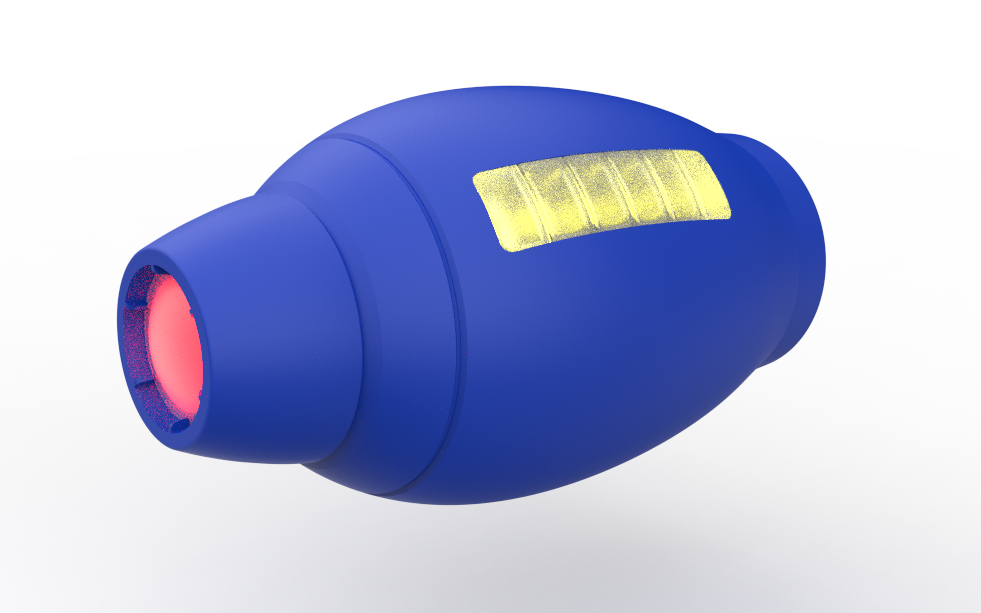
The middle body, or main body, on the left side contains a replica of the yellow power bar. This part is basically a slot made in the middle body in which we modeled a PCB that contains RGB LEDs. These LEDs glow yellow. Over these LEDs, we have placed a diffuser part that makes the whole power indication section look like the actual Mega Man gauntlet yellow bar.
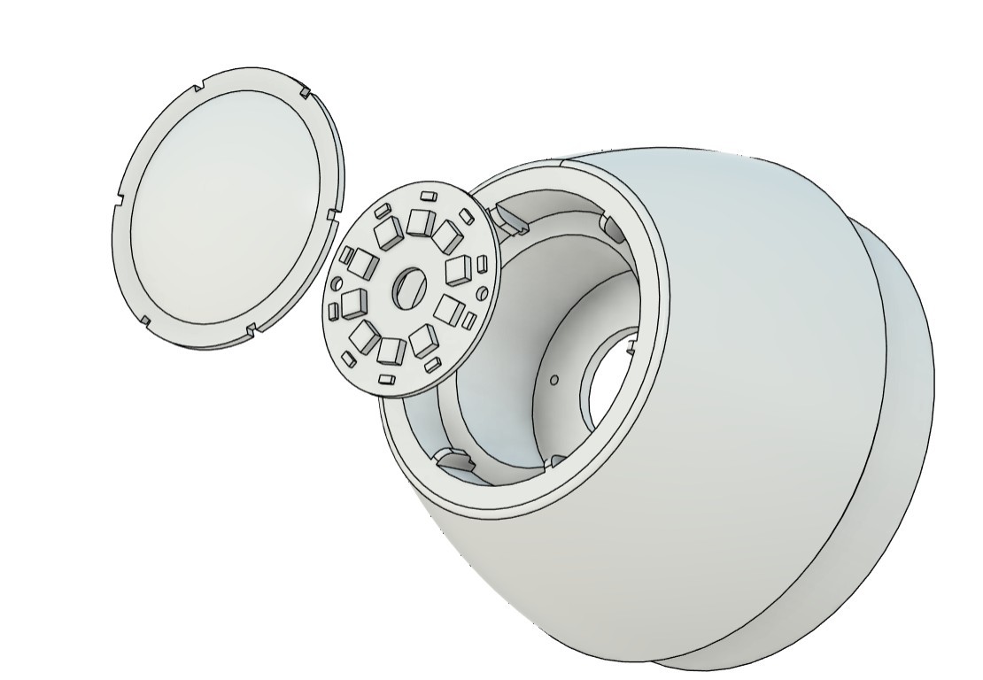
Similarly, the front part contains the blaster PCB, which has a regular red LED. Over this LED, we have modeled a diffuser that is held in place using snap locks.
The handle grip is modeled to hold a push switch. We took the concept for this from a drill handle, which contains a button in a similar way. The handle grip contains four screw bosses that are used to secure it in place inside the main body. In the main body, we have made a slot in which the handle grip slides into place, which makes the assembly very easy. It is basically a place-and-drop assembly. When the handle is placed inside, four M2 screws are added, which join the handle with the screw bosses inside the main body.
The back part is added and placed on the backside of the main body. Both of these parts are held together using only tolerance. Usually, we add 0.15 to 0.2 mm tolerance between two 3D-printed parts when attaching them together, but in this case, we added zero clearance between the parts, which allows us to pressure-fit both parts into position.
3D PARTS
After completing the CAD model, all 3D mesh files were exported from Fusion 360 at the highest quality and then imported into the slicer one by one for 3D printing.
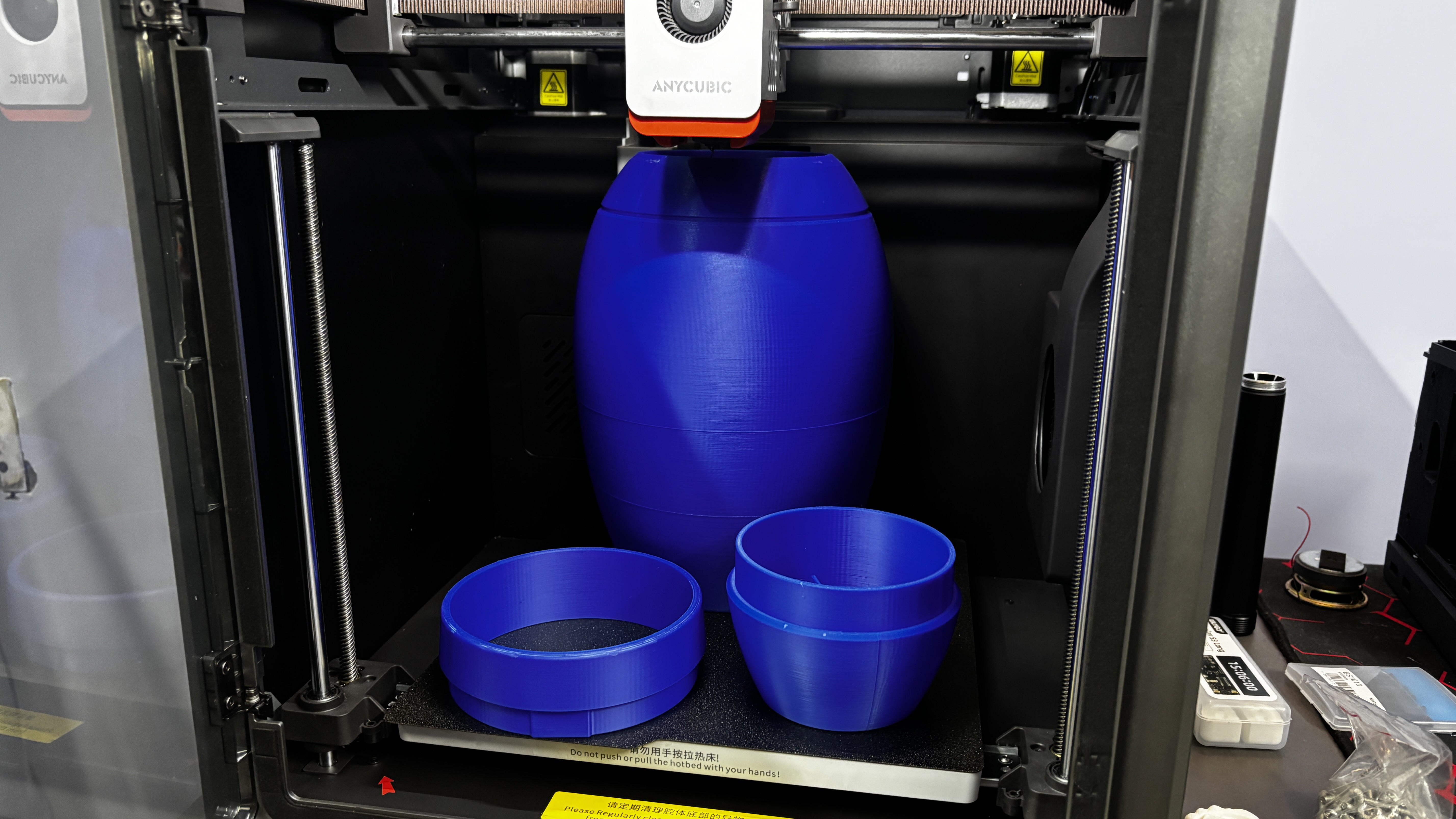
We began by printing the main body separately, as it is the largest part of the build. This single part took approximately 19 hours to print. The print was done using an Anycubic Kobra S1, using Hyper PLA with tree supports enabled for better overhang handling and easier support removal.
Using the same print settings, the back ring and front section were printed in blue Hyper PLA to maintain color consistency across the main structure.
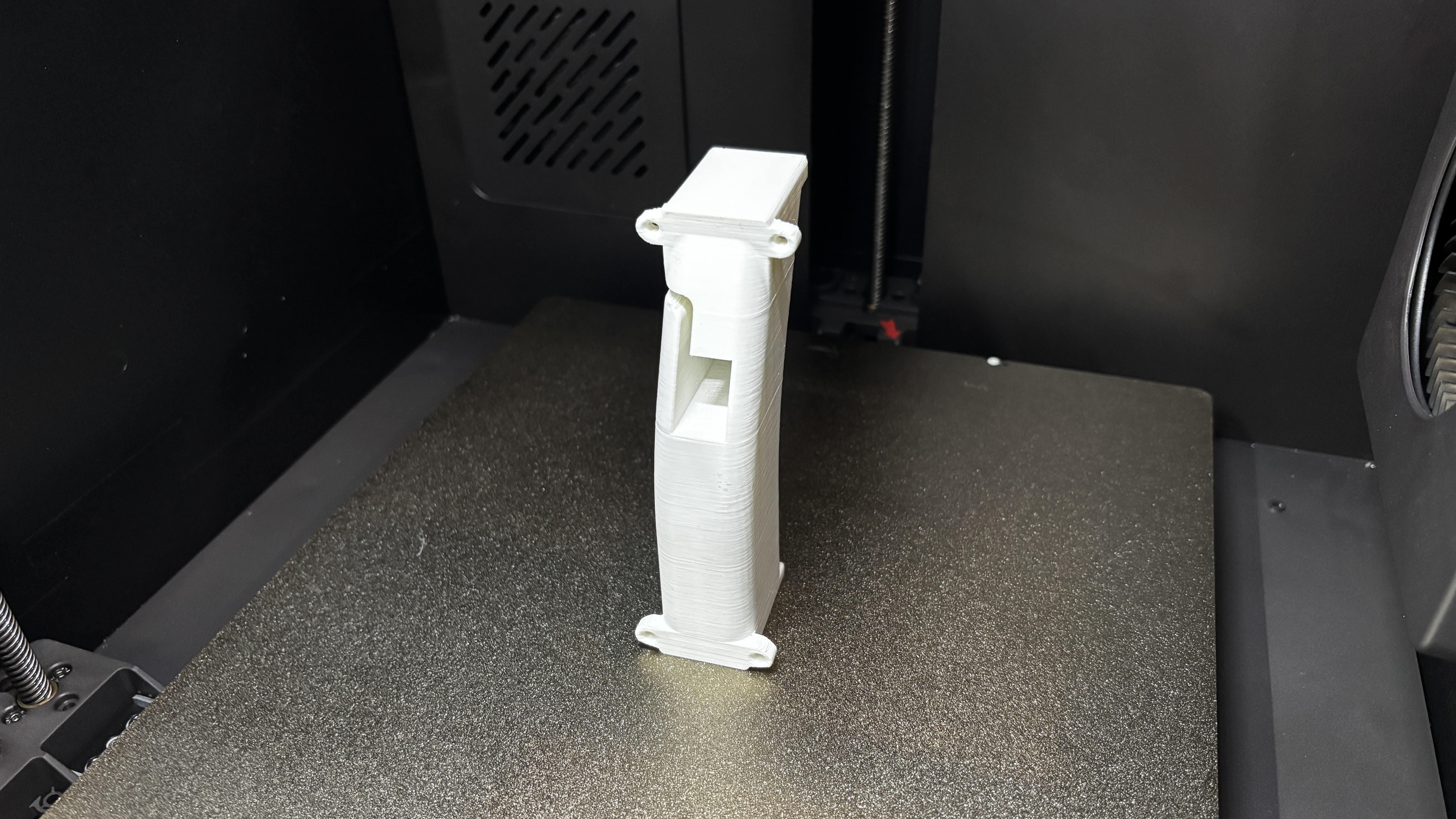
The side diffuser and front diffuser were printed using transparent Hyper PLA, allowing light to pass through evenly. The handgrip was printed in white Hyper PLA for contrast and comfort.
Tree supports were used for all parts, which made support removal easy and resulted in clean prints. Thanks to the high print quality, none of the parts required any post-processing or surface finishing before assembly.
PCB DESIGN
For this project, we designed a total of three PCBs: the main circuit, which acts as the driver and power board of the project; the side power indicator board, which consists of WS2812B LEDs to imitate the side yellow power bar; and the front blaster PCB, which contains a red LED that imitates the blast.
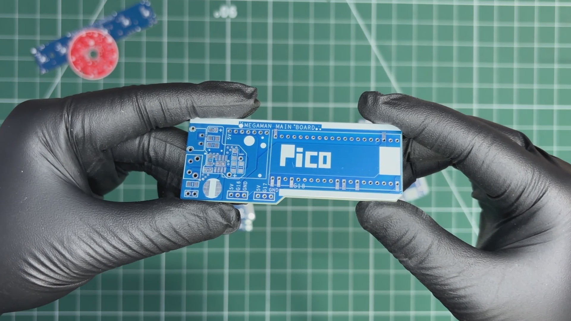
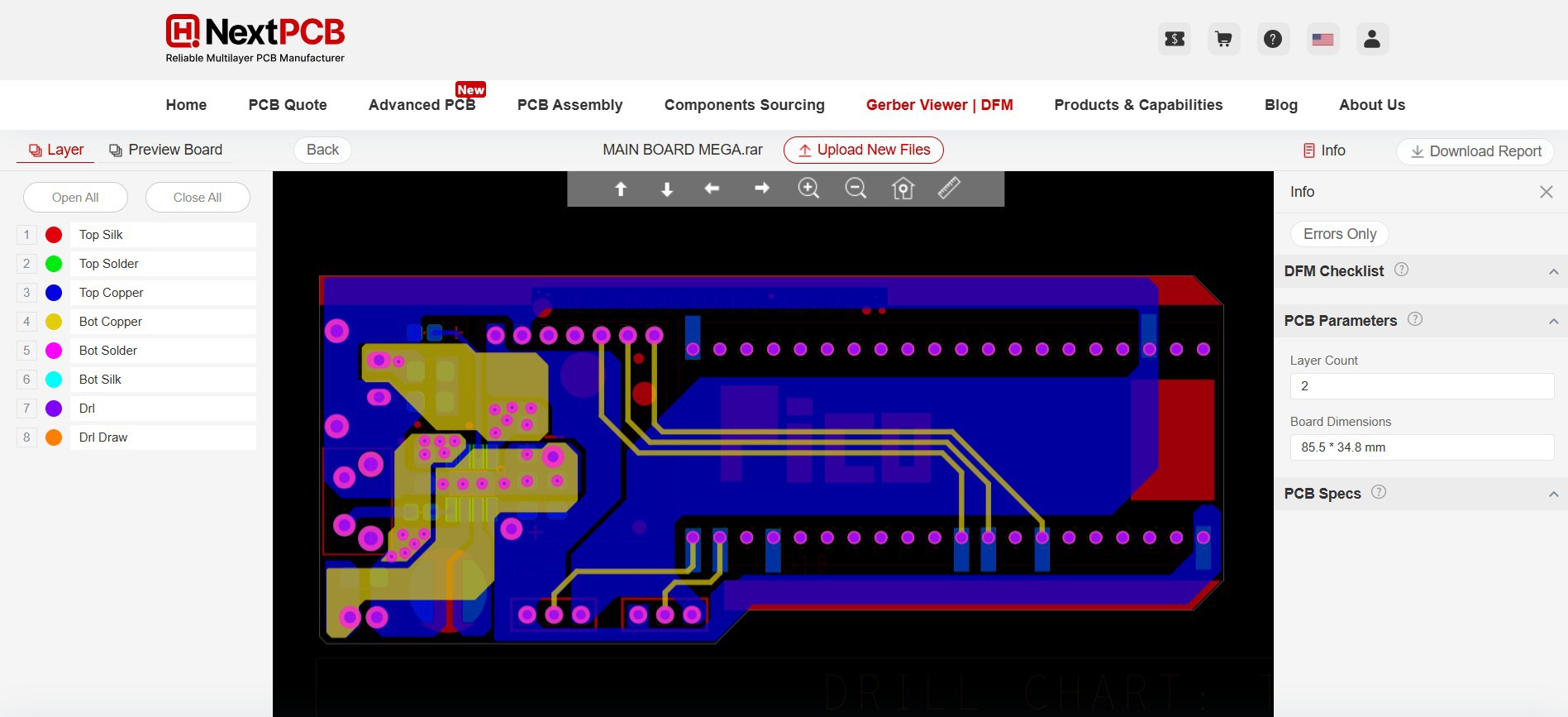
MAIN CIRCUIT
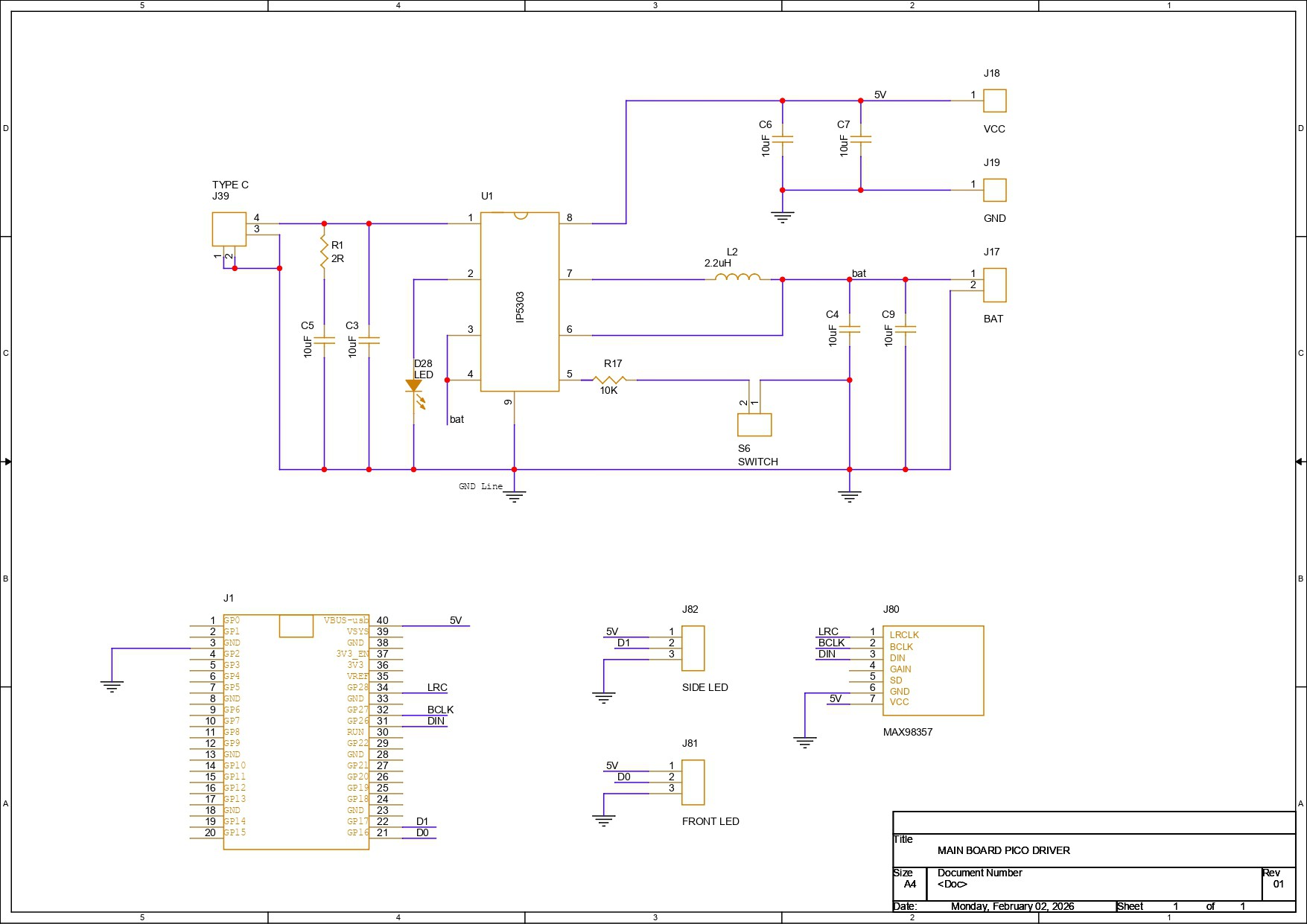
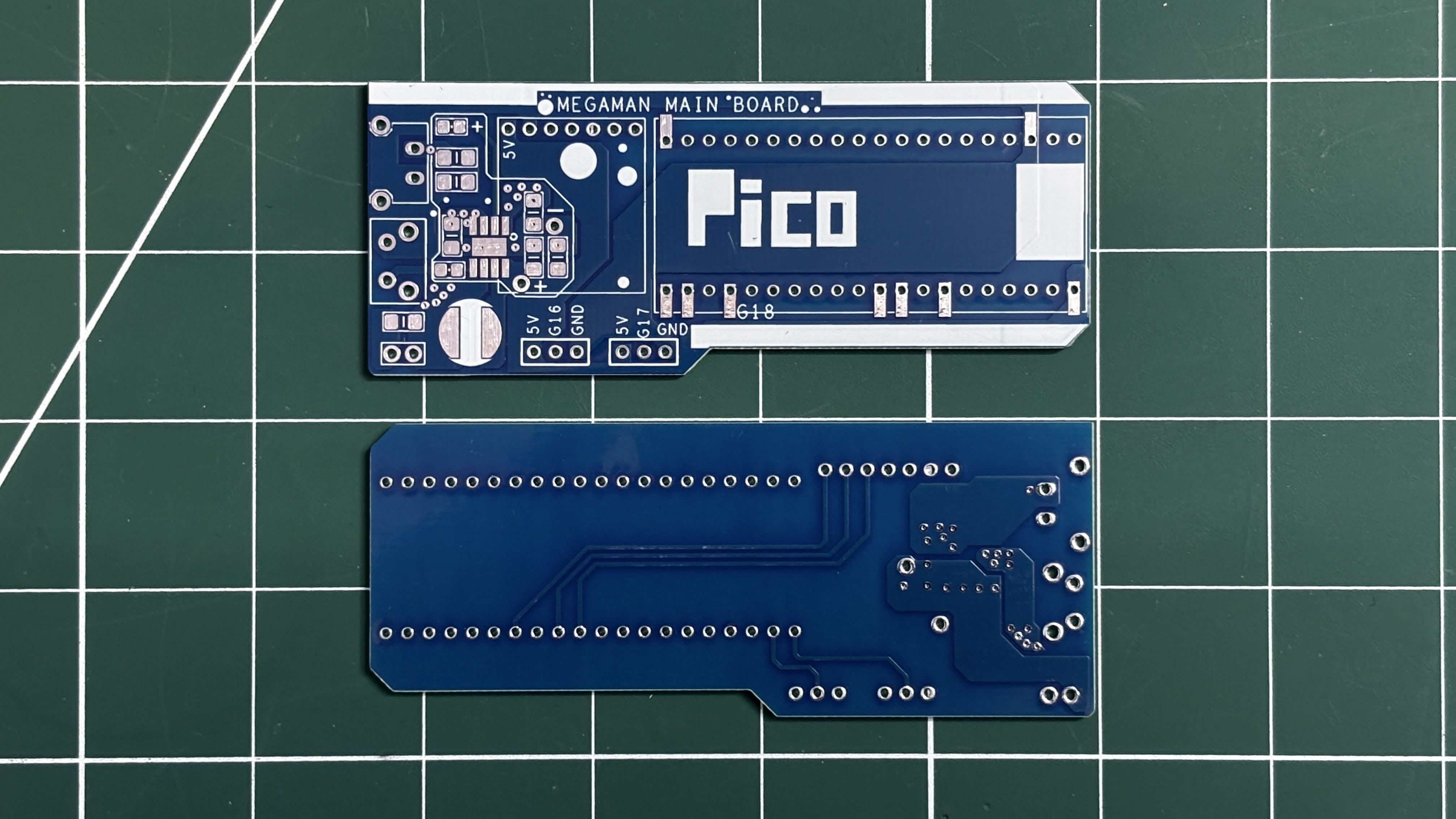
The main circuit consists of a power management IC setup paired with a Raspberry Pi Pico. Let’s have a brief breakdown of the circuit schematic.
We are using the Pico to control all our electronics, such as the front blaster PCB, side LED indicator PCB, push button, and audio amplifier—all of which are connected to the Pico.
For power, we wanted to use a LiPo cell, as it can easily fit inside the blaster. However, the Pico and other electronics require a stable 5 V, while a LiPo cell outputs only 3.7 V. To solve this, we used a power management IC, specifically the IP5306, which takes a 3.7 V lithium cell as input and provides a stable 5 V, 2 A output. It also includes complete charging and discharging circuitry, along with indicator LEDs that show battery charging status, full charge, and low battery conditions.
For adding peripherals such as the front blaster LED, side LED, and audio module, we added connector terminals on the PCB.
- CON3 provides 5 V, GND, and GPIO17 for the side LED indicator.
- Another connector provides 5 V, GND, and GPIO16 for the front blaster LED.
- CON2 is used for the push switch, with GND and GPIO15 connections.
Additionally, we added a footprint for a MAX98357A audio amplifier, but in the final build, we ended up using a PAM8403 audio amplifier with the Pico.
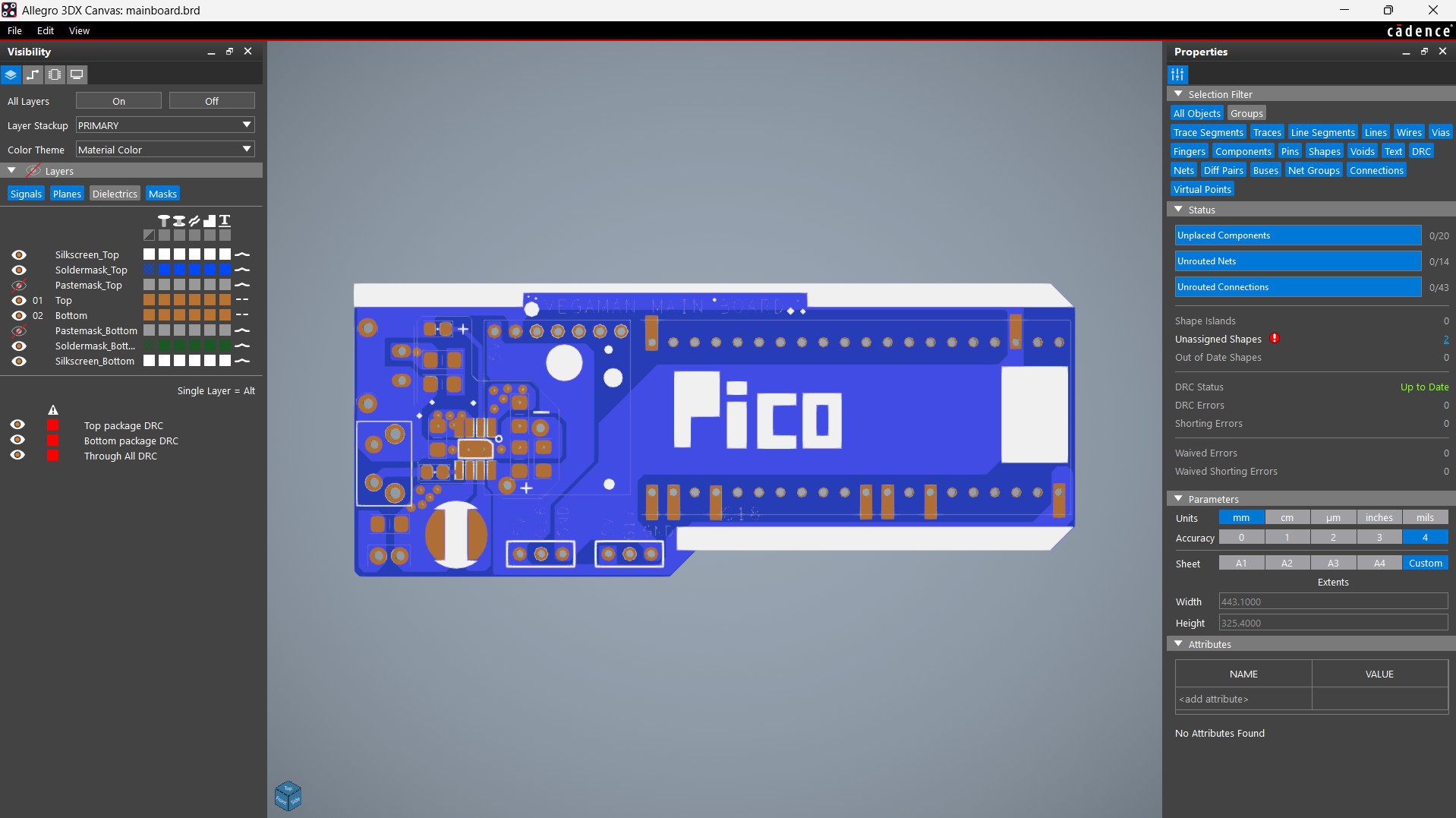
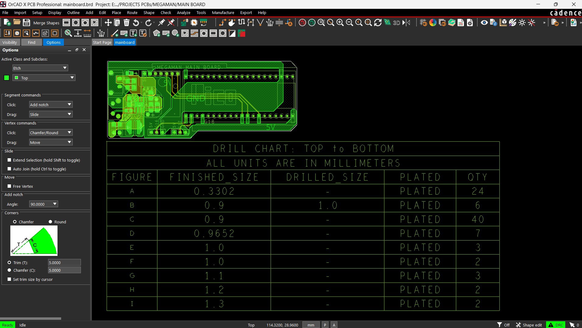
After finalizing the PCB, we converted the schematic into a PCB file. The board outline and component placement were all done by following the PCB CAD file we modeled in Fusion 360.
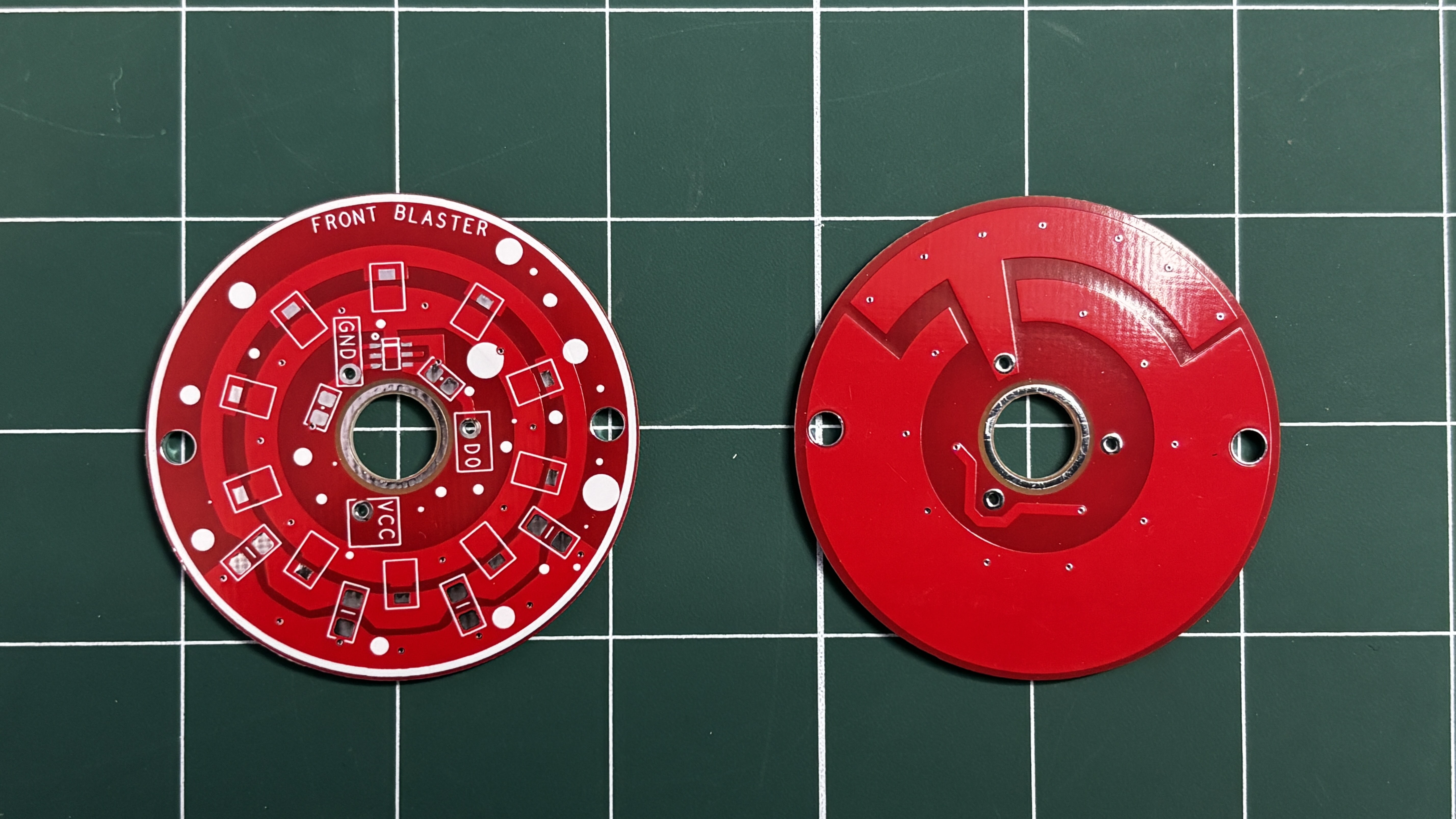
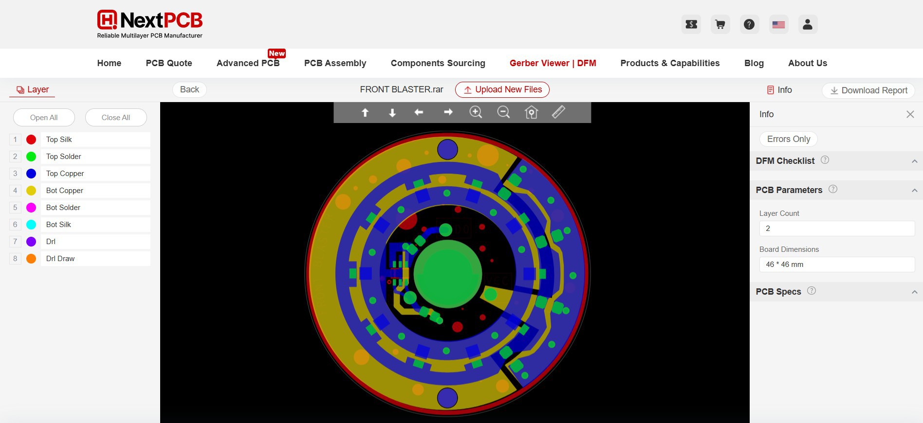
FRONT BLASTER
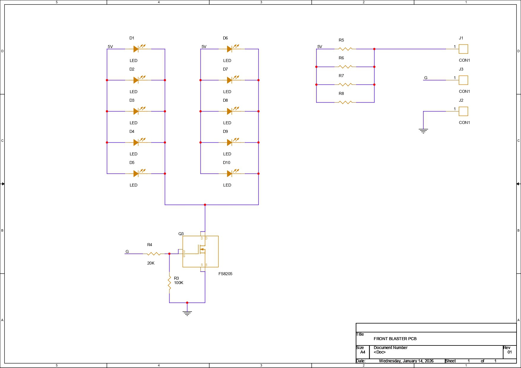
The front blaster PCB is unique. We have used 10 red LEDs in 2835 packages, all connected in parallel, with each LED drawing around 0.1 W of power. One or two LEDs can be directly connected to a GPIO pin, but using this many LEDs is not recommended, as it can damage the board.
To prevent this, we used an N-channel MOSFET as a switching setup to drive the LEDs. The VCC terminal is connected to the anodes of all the LEDs, while the cathodes of the LEDs are connected to the drain of the MOSFET IC, which in our case is the 8205S. The source of the MOSFET is connected to GND.
We have added two 10 kΩ resistors: one is connected between the DIN pin and the gate of the MOSFET, and the other is connected between the gate and source. Additionally, we have added four 1206-package current-limiting resistors between VCC and the anodes of the LEDs. These resistors limit the current passing through the LEDs and protect them from overcurrent.
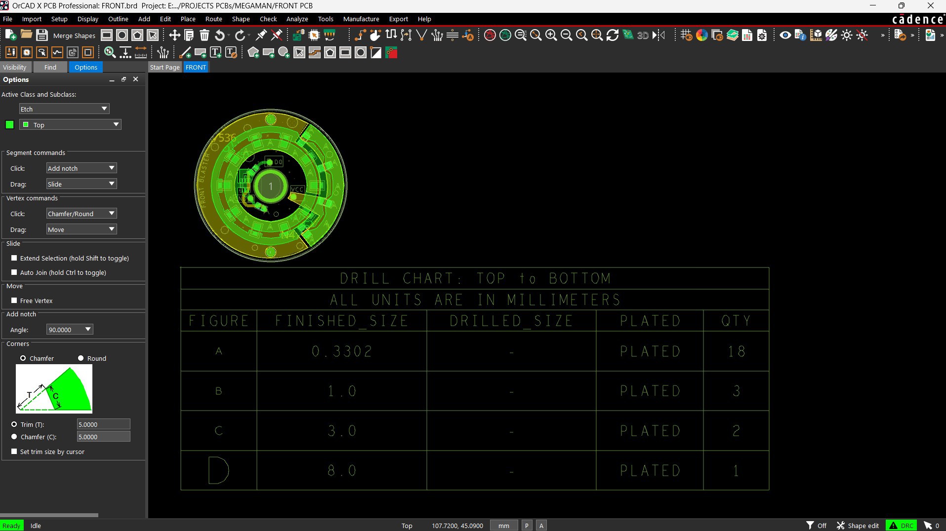
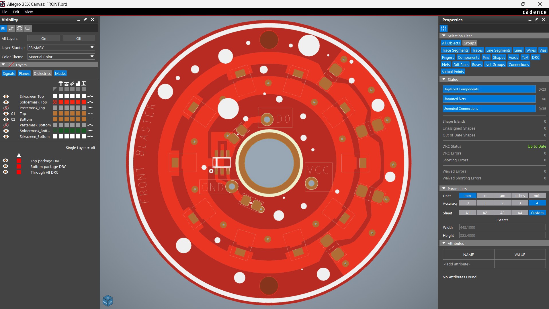
For this board, the LEDs are placed in a circular pattern, which is time-consuming to design directly in PCB CAD software. To simplify this, I exported the DWG file of the entire board from the CAD model and imported it into my PCB CAD software. Using the LED outlines from the DWG file as a reference, I aligned and placed the SMD LEDs accurately. This allowed us to create the front blaster PCB exactly as per the CAD model.
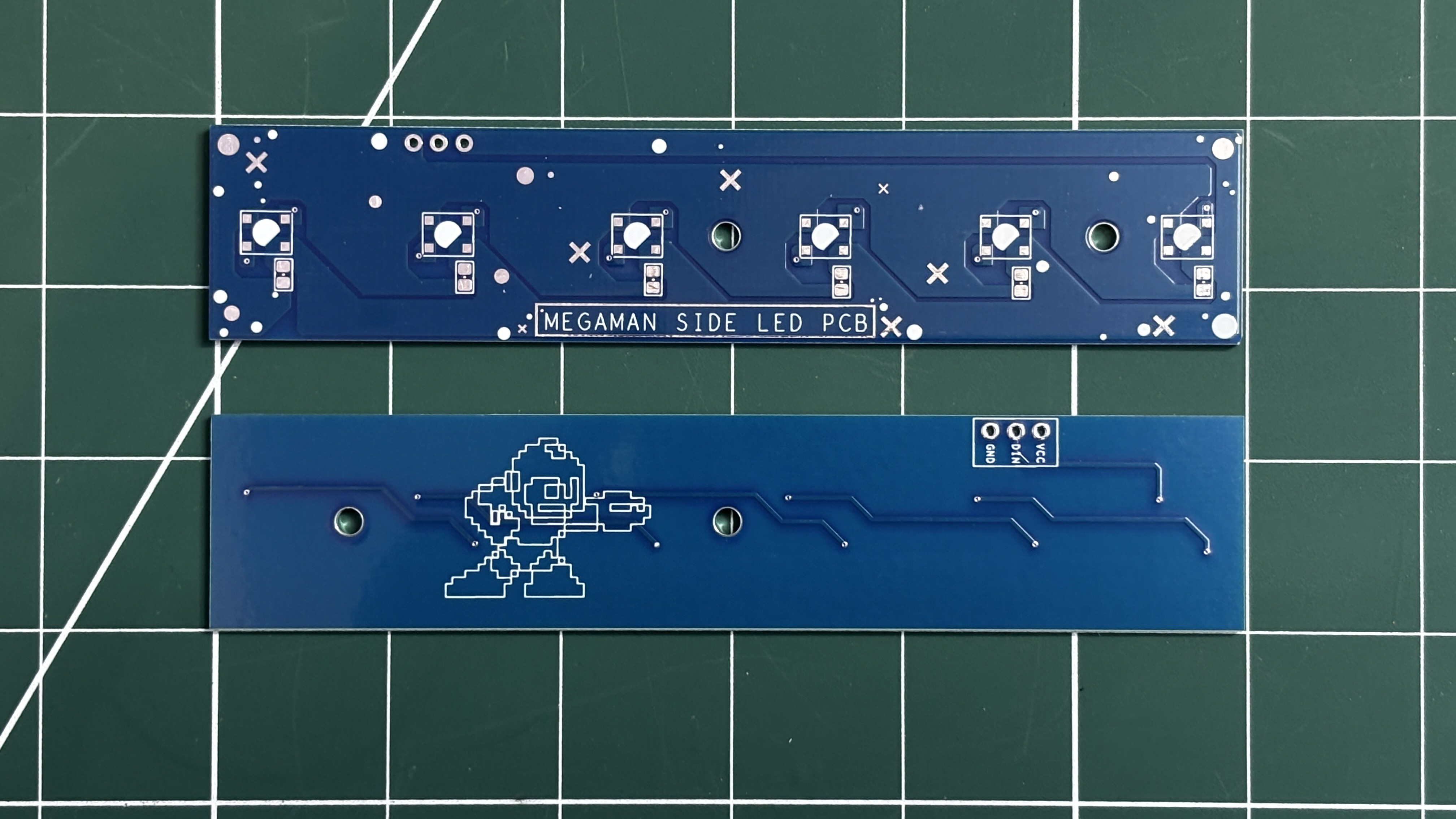
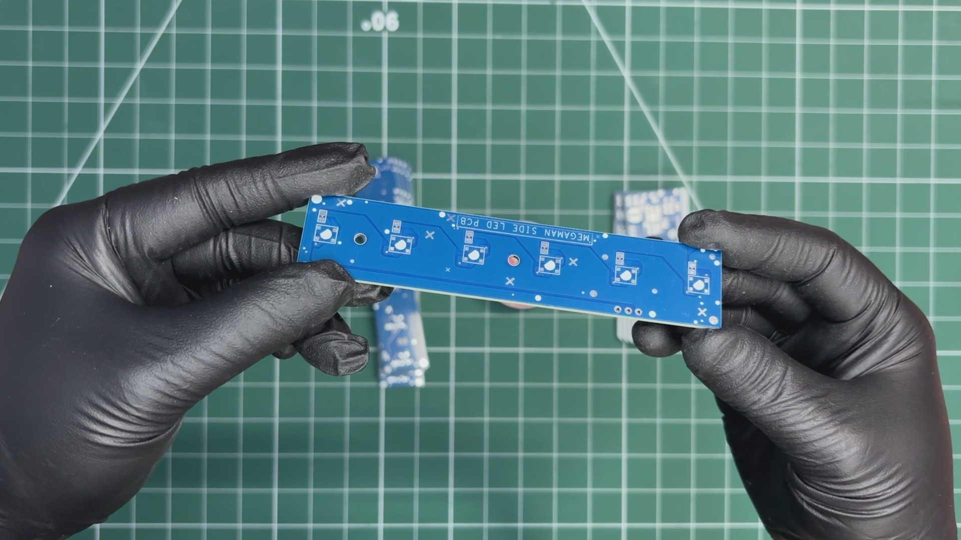
SIDE POWER INDICATOR
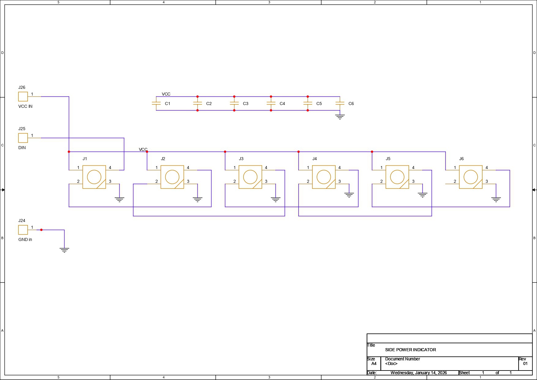
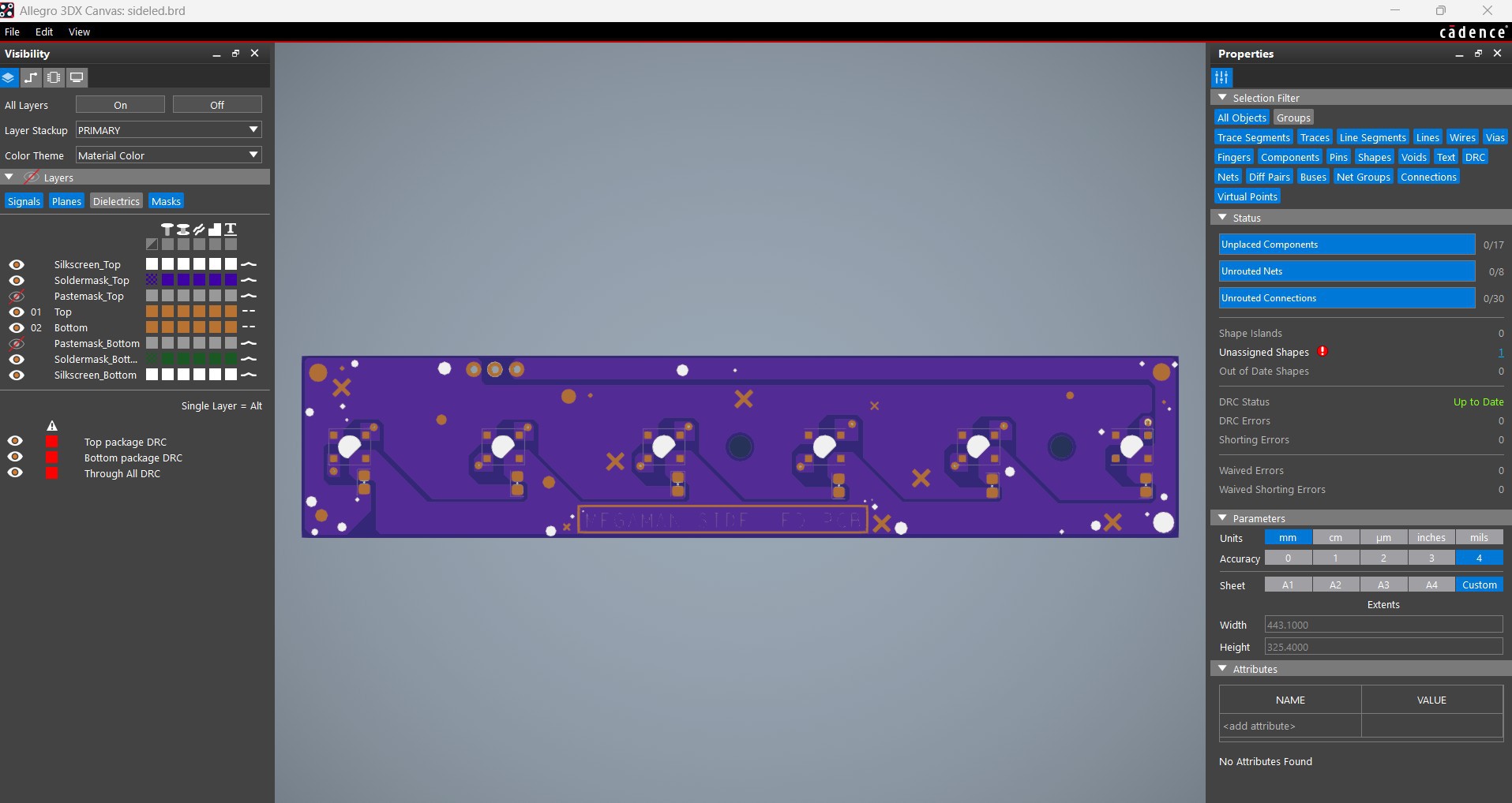

For the side power indicator, we have used six WS2812B LEDs, all linked together in their usual configuration. The DOUT of the first LED goes into the DIN of the second LED, the DOUT of the second LED goes into the DIN of the third LED, and this continues up to the sixth LED.
Each LED is paired with a 100 nF decoupling capacitor, which is placed close to the LED’s VCC and GND pads during the PCB design process to ensure stable operation.
For the board outline, mounting holes, and LED placement, we used the CAD model as a reference.
NextPCB PCB SERVICE

After completing the PCB design, Gerber data for all three PCBs was sent to HQ NextPCB, and an order was placed for two boards with a blue solder mask and one board with a red solder mask.
After placing the order, the PCBs were received within a week, and the PCB quality was pretty great.
In addition, I have to bring in HQDFM to you, which helped me a lot through many projects. Huaqiu’s in-house engineers developed the free Design for Manufacturing software, HQDFM, revolutionizing how PCB designers visualize and verify their designs.
Take advantage of NextPCB's Accelerator campaign and get 2 free assembled RP2040-based PCBs for your innovative projects.
https://www.nextpcb.com/blog/rp2040-free-pcba-prototypes-nextpcb-accelerator
This offer covers all costs, including logistics, making it easier and more affordable to bring your ideas to life. SMT services can be expensive, but NextPCB is here to help you overcome that hurdle. Simply share your relevant project, and they'll take care of the rest. Don't miss out on this amazing opportunity to advance your tech creations!
HQDFM: Free Online Gerber Viewer and DFM Analysis Tool
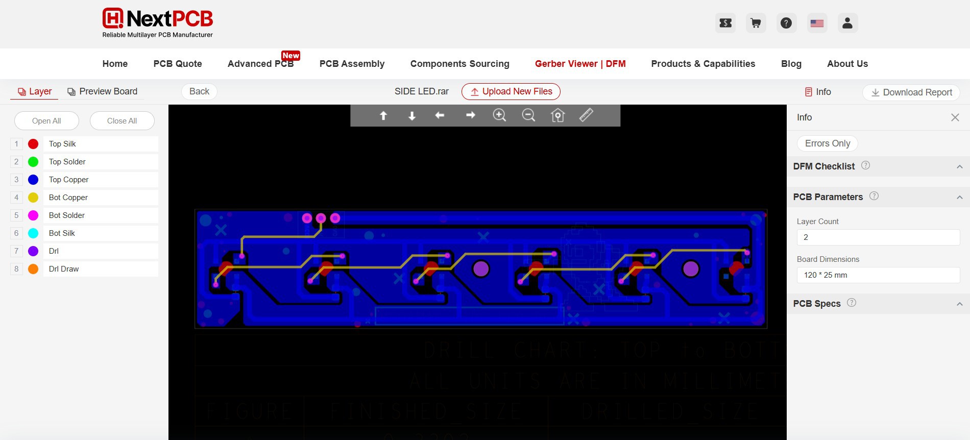
Also, NextPCB has its own Gerber Viewer and DFM analysis software.
Your designs are improved by their HQDFM software (DFM) services. Since I find it annoying to have to wait around for DFM reports from manufacturers, HQDFM is the most efficient method for performing a pre-event self-check.
This is what I see in the online Gerber Viewer. It's decent for a quick look but not entirely clear. For full functionality—like detailed DFM analysis for PCBA—you’ll need to download the desktop software. The web version only offers a basic DFM report.
With comprehensive Design for Manufacture (DFM) analysis features, HQDFM is a free, sophisticated online PCB Gerber file viewer.
With over 15 years of industry experience, it offers valuable insights into advanced manufacturing processes. If you’re looking for reliable PCB services at a budget-friendly price, HQ NextPCB is definitely worth checking out.