 mircemk
Cathode Ray Tube (CRT) displays a clock face—either digital or analog—using the screen's ability to draw lines based on voltage. The "X" (horizontal) and "Y" (vertical) inputs of the oscilloscope are controlled by the circuit, and by rapidly changing these voltages, the circuit "draws" numbers or clock hands on the screen. In one of my previous videos , I presented the simplest way to make such a clock yourself.
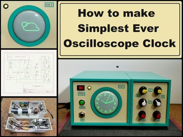
However, its construction requires relatively solid knowledge in the field of electronics and high voltage, and it's also quite expensive.
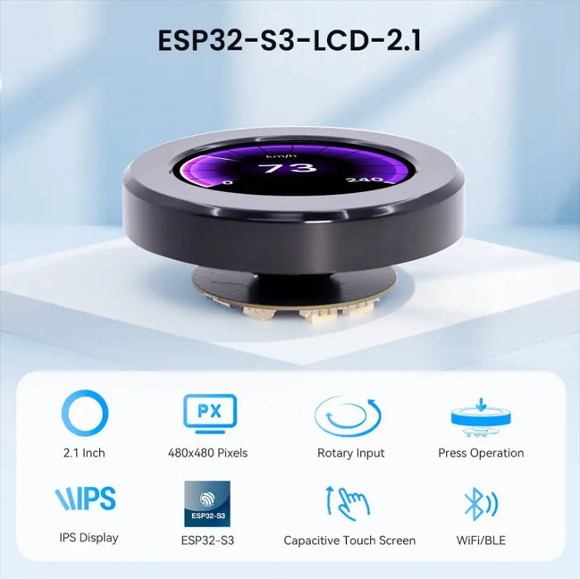
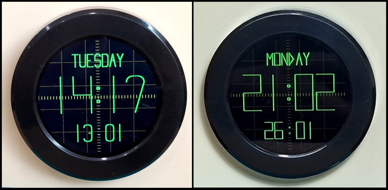
This time I will show you an extremely simple way to make an "oscilloscope clock" on a 2.1 Inch Crowpanel circular display that completely visually imitates the original. Starting from the circular shape of the Display, through the original green color, the marked scale, up to the shape, the way the lines are displayed and illuminated, irresistibly reminds of a CRT Tube.
It is also desirable to mount it in a suitable housing that would resemble a retro CRT oscilloscope for the effect to be maximum.
This project is sponsored by PCBWay . From concept to production, PCBWay provide cutting-edge electronic design solutions for global innovators, Including hardware design, software development, mechanical design, product testing and certification. PCBWayengineering team consists of experienced engineers in electronics, embedded systems, and product development. They successfully delivered hundreds of projects across industries such as medical devices, industrial automation, consumer electronics, smart home, and IoT.

So, to make this clock, no soldering or external components are required. The round display contains a built-in ESP32S3 microcontroller with Wi-Fi and Bluetooth capabilities. We only need to upload the given code, and the device is ready in a few minutes. But before that, certain settings should be noted.
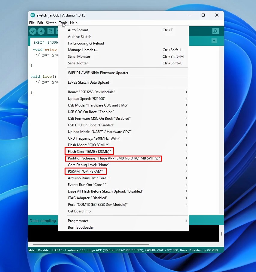
First, you need to use Arduino IDE version 1.8.15 or later. Then you need to install Newest ESP32 Core. Now in Tools-Board-ESP32 Arduino, we need to select ESP32S3 Dev Module. In this board, we need to make several changes to the properties: Flash Size 16MB, Partition scheme- Huge App, and PSRAM - OPI PSRAM.
You also need to install the Arduino_GFX_Library. Now we can compile and upload the code without errors. As for the code, the basic settings are located at the beginning, here you need to insert the Wi-Fi credentials, the NTP Server, as well as the definition of the display colors.

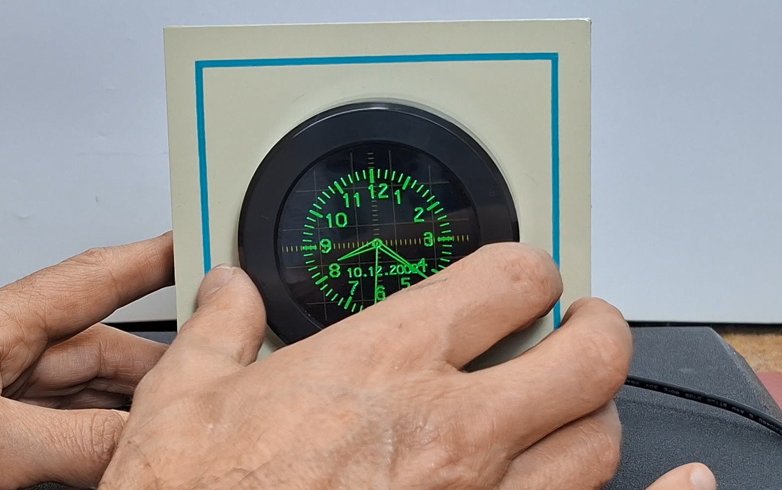
Now let's see how the device works in real conditions. Immediately after turning on the clock connects to the Wi-Fi network and gets the correct time from the NTP server. Then an analog clock appears on the display in the style of an Oscilloscope clock with a characteristic green color. Even a "glow" effect has been added when drawing the characters, but unfortunately it is almost not noticeable in the video recording. To make it even closer to the original, I added an option to change the dimensions of the clock using the rotary encoder that is part of the display module.
In this way is simulated a change in the amplitude of the signals fed to the X and Y inputs on the original oscilloscope. By pressing the display (the button on the rotary encoder), a digital oscilloscope clock is activated, drawn with arcs and straight lines, which is characteristic of the original oscilloscope version. Here, as before, I introduced a "glow" effect. By pressing again, we return to the analog clock. As for the digital clock, in the first version of the code, the content was formed only by drawing straight lines, which is also characteristic of these devices. At the end of the text, both versions of the code are given.
And finally a short conclusion. By combining the vintage aesthetics of a CRT oscilloscope with modern ESP32 hardware, this project proves you don't need dangerous high voltage to enjoy the classic look of a vector clock....
Read more »
 alberto nunez
 Jonathas Barbosa
 Frederic L
 Arnov Sharma