 dylan zheng
Another Jumperlink Example
(I²C OLED Demo)
In this example, I’ll demonstrate how Jumperlink handles an I²C bus setup.
The module used here is an SSD1306 128×64 0.91" OLED display (I²C version) — a common and inexpensive module easily available from AliExpress and other online suppliers.
This OLED module exposes four signals:
- VCC
- GND
- SCL (I²C Clock)
- SDA (I²C Data)
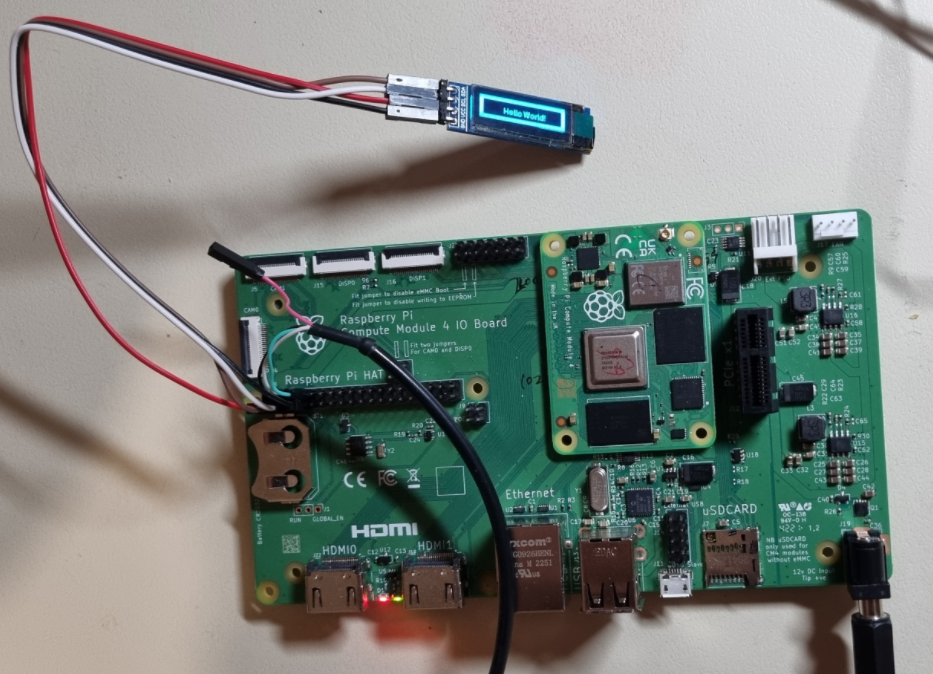
To make the comparison fair, I first built the test setup using traditional jumper wires.
Then I rebuilt the setup using Jumperlink instead of traditional jumper wires.
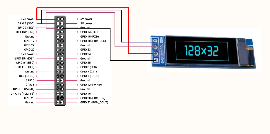
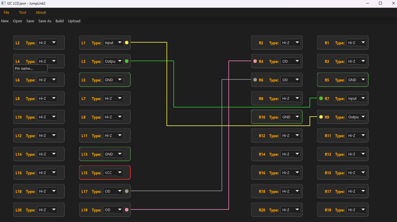
The signal mapping is configured as follows:
- R4 → SDA signal (from pin 3 of connector J8 on the I/O board)
- R6 → SCL signal (from pin 5 of J8)
- R10 → GND (from pin 9 of J8)
On the left side of Jumperlink, pins L13, L15, L17, and L19 are assigned and connected to the OLED module (VCC, GND, SCL, SDA).
In this example, we also need UART console access for debugging:
- TXD (pin 8 of J8)
- RXD (pin 10 of J8)
Since connector J8 is now occupied by Jumperlink, those UART signals can no longer be accessed directly from the original header. Instead of running extra jumper wires, I simply re-linked them internally within Jumperlink and routed them to different available pins on the left side — in this case, L1 (TXD) and L3 (RXD).
No rewiring. No signal conflict. Just reconfiguration.
Below is the fully linked circuit configuration.
The running result is:
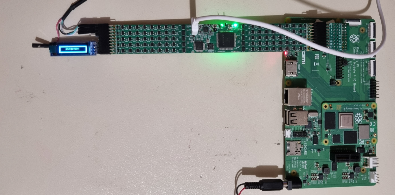
The final wiring is clean, compact, and easy to follow.
As demonstrated, Jumperlink fundamentally improves how two modules are interconnected. It removes cable clutter and replaces it with a structured, software-defined configuration. Connections become faster to set up, easier to maintain, and far simpler to document and share with others.
Discussions
Become a Hackaday.io Member
Create an account to leave a comment. Already have an account? Log In.