0%
0%
FMCW Radar
Learning to design and build a 24GHz FMCW Radar from first principles
 Darren Winter
Become a Hackaday.io member
Already have an account? Log in.
Just one more thing
To make the experience fit your profile, pick a username and tell us what interests you.
Pick an awesome username
hackaday.io/
Your profile's URL: hackaday.io/username. Max 25 alphanumeric characters.
Pick a few interests
Projects that share your interests
People that share your interests
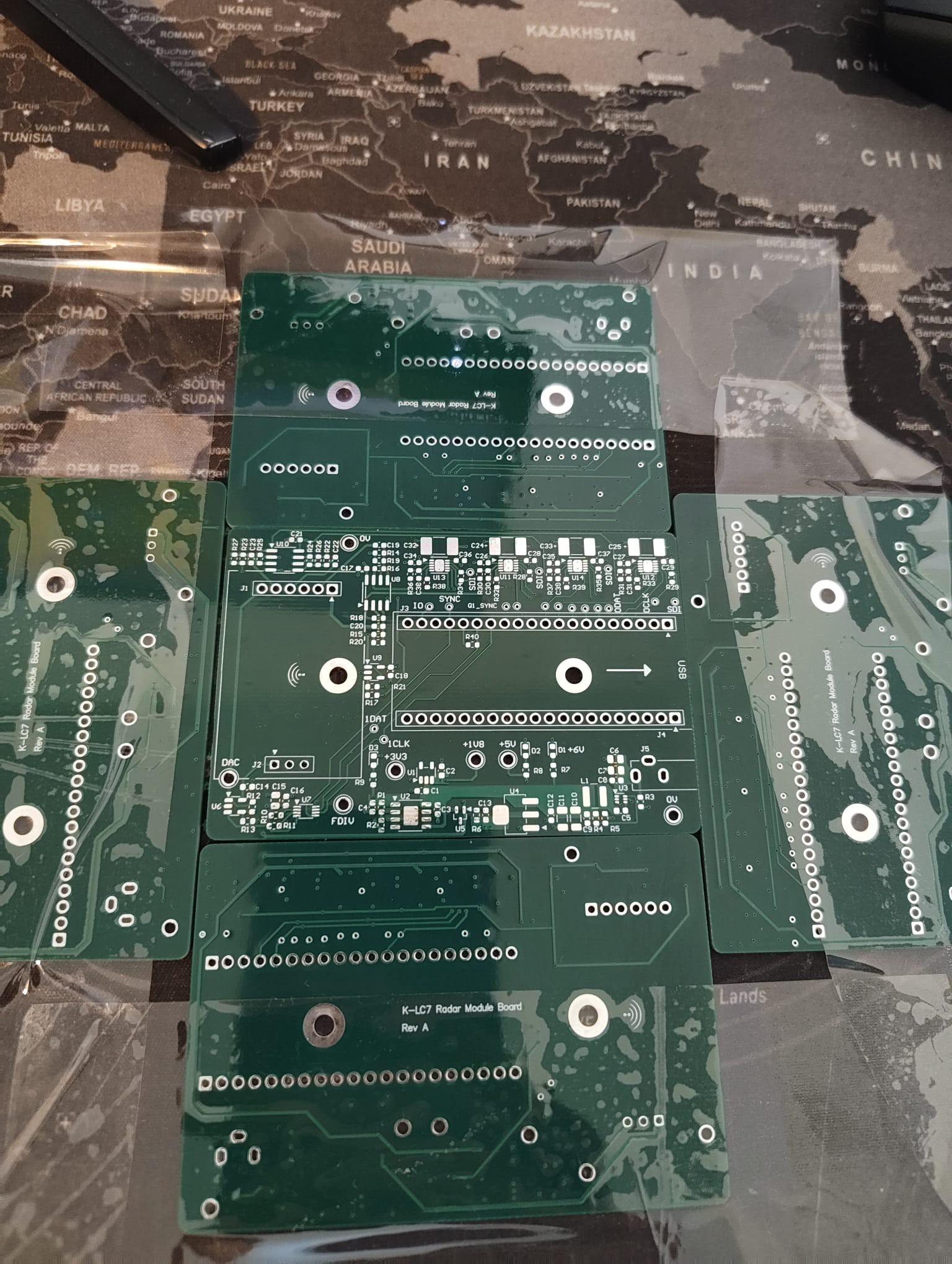
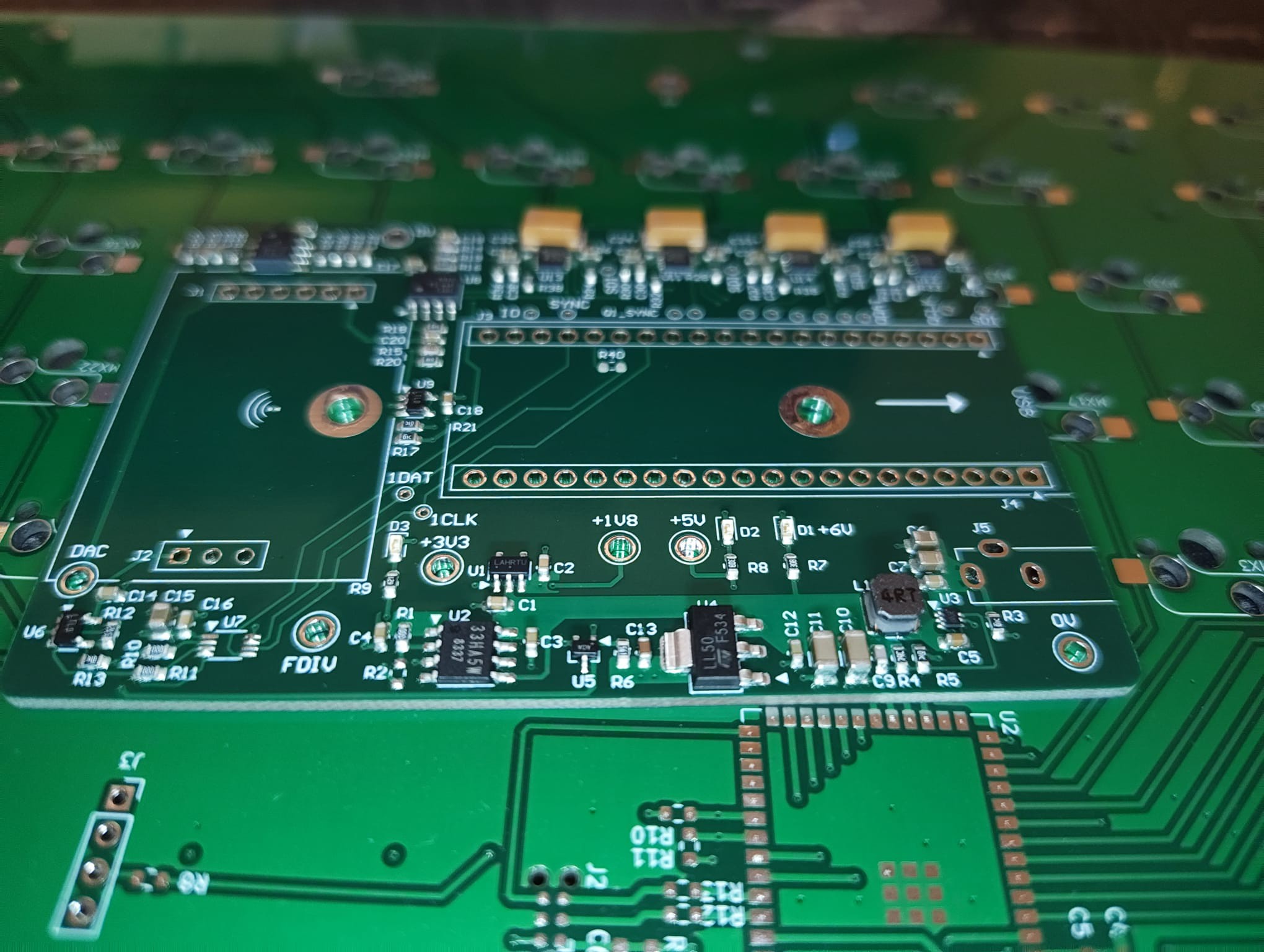
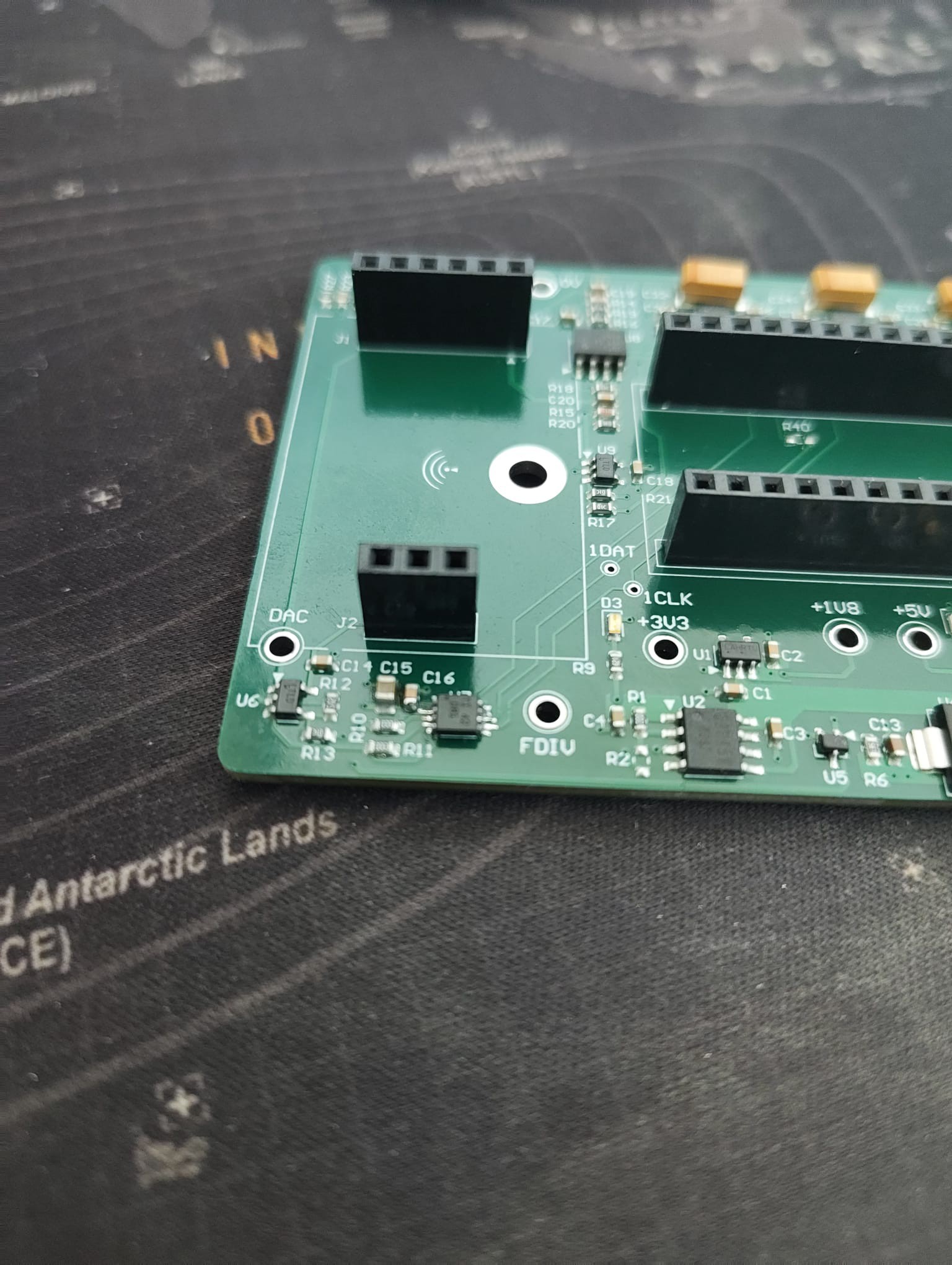
 During the design of the PCB the same rules applied to any other and that was keeping areas seperate on the board where you can and short traces. I certainly was a bit nervous when routing this as the analog portion does not have much wiggle room and the radar output is already quite close to the noise floor.


 Dan Kisling
 Jesse R
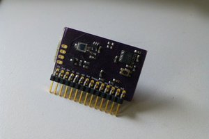
 doctek
 Martin