Povilas Dumcius
The Question
Addressable LEDs like the WS2812 are practically synonymous with microcontrollers. You write code, you send timed pulses, the LEDs light up. But strip away the microcontroller entirely no Arduino, no ESP32, no code at all and can you still talk to these LEDs using nothing but oscillators, counters, and logic gates?
Turns out, yes. But it took a while.
What the WS2812 Actually Wants
The protocol is deceptively simple. Each LED needs 24 bits of color data 8 bits each for green, red, and blue. A logic one is a long high pulse (~700 ns) followed by a short low (~600 ns). A logic zero is a short high (~350 ns) followed by a long low (~800 ns). After sending all your data, you hold the line low for 50 µs and the colors latch. First LED in the chain eats its 24 bits and passes the rest downstream.
Simple to describe. Less simple to build from scratch without a processor.
Clock Generation: The 555 That Wasn't
The target frequency is around 800 kHz. The obvious first attempt was a 555 timer. I tried the classic astable configuration, modified circuits, bipolar, CMOS. Every time, parasitic capacitance capped me at around 400 kHz. Couldn't break through it no matter what I did.
So I ditched the 555 entirely and went with a Schmitt trigger oscillator using a 74HC14. Capacitor on the input, feedback resistor, and the output is a clean square wave. Got roughly 720 kHz, and the pulse widths happened to land right in the WS2812 logic-one timing window — highs around 650 ns, lows around 740 ns.
One oscillator. Two problems solved.
Building the Logic Zero Pulse
The clock signal already works as the logic-one pulse train. For logic zero, I need shorter high pulses. I buffered the main clock through two inverters and added an RC delay to shift the phase slightly. The result wasn't what I expected the delayed signal looked nearly identical to the original, just offset.
But I noticed both signals had their highs overlapping for about 340 ns. Running them through an AND gate extracted exactly that overlap: a pulse that's high for ~340 ns and low for ~900 ns. That's the logic zero.
I now had two pulse trains: long pulses (logic one) and short pulses (logic zero), both synchronized to the same clock.
Counting to 24
Each LED needs exactly 24 bits 8 green, 8 red, 8 blue, in that order. A 74HC binary counter handles this. On every clock cycle, the counter advances by one. When it hits 24 (both the 8 and 16 outputs go high), an AND gate resets it back to zero.
While it's counting, the counter's bit positions naturally flag which color is active. Bits 0–7: position 8 is low, position 16 is low that's green. Bits 8–15: position 8 is high that's red. Bits 16–23: position 16 is high that's blue.
For green, since there's no single bit that uniquely identifies it, I inverted positions 8 and 16 and ANDed them together. When both are low, the output goes high green time.
These three identification signals are the backbone of the whole design. They act as envelopes windows of exactly 8 clock cycles during which a particular color can be written.
Color Selection and Mixing
Each color channel has a button. When pressed, it activates an AND gate that passes the logic-one pulse train during that color's identification window. When not pressed, the logic-zero pulse train passes instead.
To mix colors, all three button outputs feed into an OR gate. If I hold red and blue simultaneously, the data stream contains logic-one pulses during both the red and blue windows, and logic-zero during green. The LED displays purple.
The final output combines both pulse trains through one more AND gate. When no button is pressed, the output is always short pulses (all zeros LEDs off). Press a button and the short pulses get replaced with long ones at exactly the right position in the bitstream.
The Reset Signal
The WS2812 protocol requires a 50 µs low period between data frames to latch the colors. I added a second binary counter, clocked by the reset pulse of the first one (which fires every 24 bits). When this counter reaches 64 — meaning 64 LEDs worth of data have been sent it pulls the data line low through an inverter and AND gate. The line stays low until the counter rolls back around, creating the required gap.
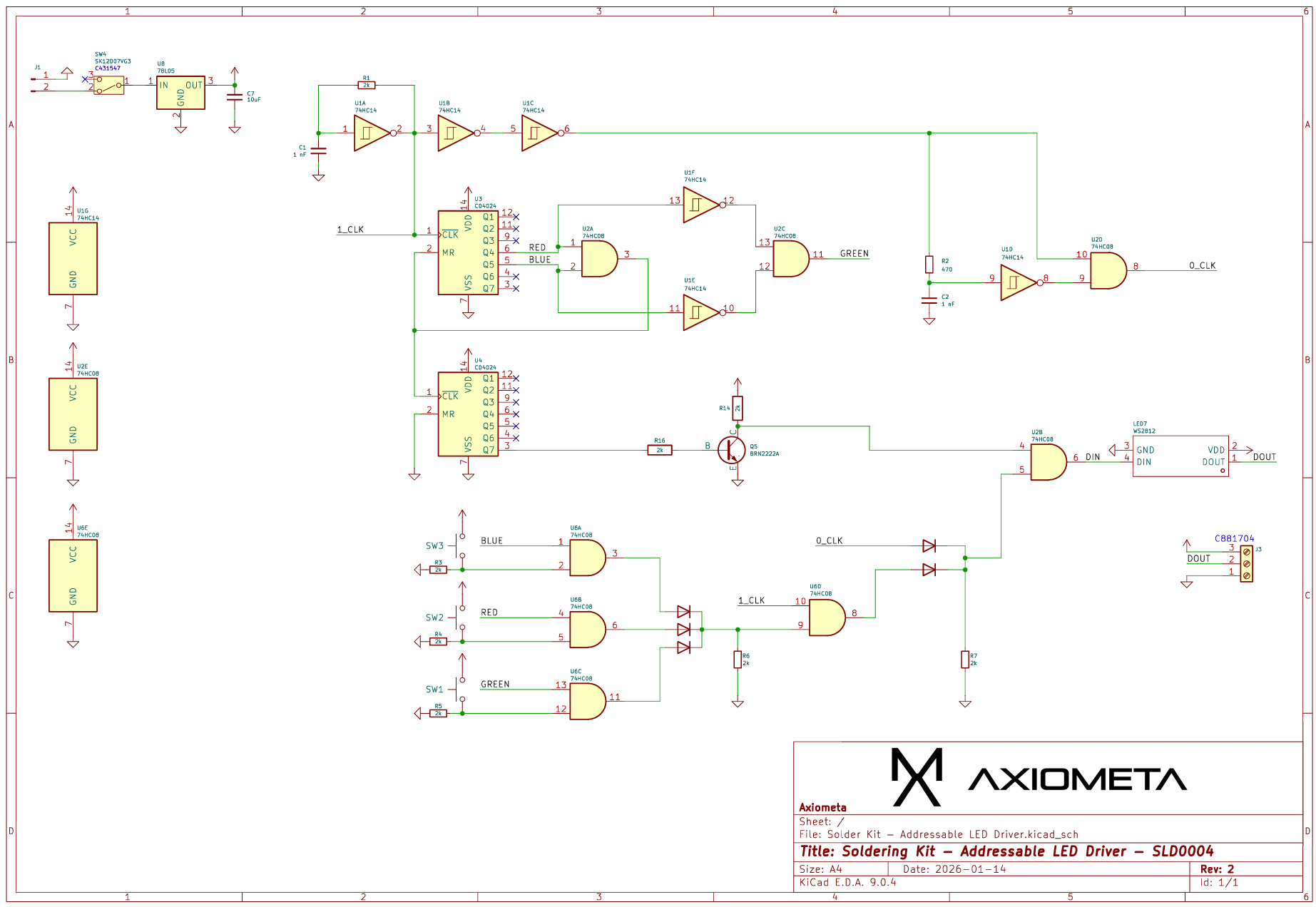
The Full Signal Path
- Schmitt trigger oscillator → ~720 kHz clock (also serves as logic-one pulse train)
- Phase-shifted AND gate → logic-zero pulse train (shorter highs)
- Binary counter → 24-bit cycle with color identification signals for green, red, blue
- Buttons + AND gates → on-demand color selection and mixing via OR gate
- Final AND gate → selects between long and short pulses based on button state
- Second counter → generates 50 µs reset gap every 64 LEDs
- Output AND gate → combines data with reset timing → WS2812 data stream
Results
On the breadboard, it worked eventually. That first successful color test was satisfying in a way that uploading a NeoPixel sketch has never been.
Tested on a 5×5 LED matrix: buttons for green, red, blue individually, plus mixing red and blue for purple, green and blue for cyan, all three for white. The data stream is clean enough for 64 LEDs.
Full Schematic
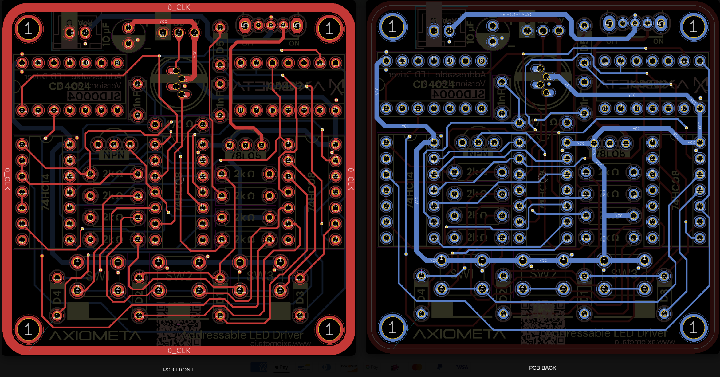
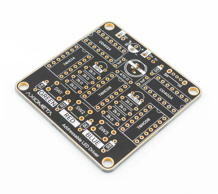
The PCB
I laid out a soldering kit version of the circuit, designed to be 55 mm × 55 mm and symmetrical. It includes a through-hole WS2812 LED on the board itself so it works standalone without an external strip. Three buttons, all the logic, and a header for connecting more LEDs if you want.
After soldering everything and spending an entire day debugging: a self-sustaining, code-free WS2812 driver. Three buttons for RGB, hold two for mixing.
24 bits. One oscillator. One counter. Some logic gates. No code.