Close
0%
0%

Cell-Lock: The modular battery assembly system

Build custom 18650 batteries in minutes, no spot welder required!

benBen
Similar projects worth following
Cell lock is a system that allows anyone to assemble cylindrical lithium-ion battery cells in nearly unlimited voltage and capacity configurations. No more searching in vain for that triangular 42-volt battery to fit in your new E-bike, or that 18v pack you need for your robot arm; easily build it yourself using off-the-shelf cells!

Each Cell-lock cap functions as both a cell holder and an electrical connector, allowing for strong, secure connections between cells, with no spot welding required. These caps are then assembled using twist locking connectors that secure each cell together and define the series/parallel layout of the battery. Once assembled, you can then attach it to your BMS using the integrated quick connect tabs.

Cell-Lock is fully open source and 100% customizable. Increasing the voltage or capacity is as simple as adding a few more cells, and you can always upgrade with new cells, or remove the old ones for easy recycling. More power to you!


The Problem:

Currently, if you want a lithium battery for your project there are essentially two options, each with their own pros and cons: buying standard size/voltage packs from manufacturers and resellers or designing building your own packs using expensive spot-welding equipment. My goal with Cell-Lock was to find the best middle ground between these two options:

Off The Shelf

Custom Build

+ Easy, plug and play if you can find the right one

+ Exactly the right voltage/shape/capacity

+ Many different chemistries, power to weight ratios

+ Use any cells you want,  much cheaper

- More expensive, can’t usually repair/upgrade

- Needs $$ equipment

- Standard shapes and voltages, no customization 

- Takes time/skill, can be dangerous

I wanted to reap the benefits of custom-building packs, without the hassle of buying zinc strips, spot welding and soldering everything together. 

The Process:

I took inspiration from standard cell holders, and begun trying to incorporate electrical connections into the overall square or hexagonal profile of these plastic parts. These initial efforts produced mixed results, with poor connections that would sometimes make it to the correct voltage, but often would work their way loose during assembly or usage. Additionally, they didn’t provide the mechanical rigidity I was looking for in the full battery. 

Initial Prototypes

I then started to design my own press fit connectors, using 3d printed parts and laser cut copper sheet to connect the batteries, which was a significant improvement, but still suffered from issues when attaching more than 4 or 5 cells together. It was around this point where I got stuck, and started to work on other projects.

As it happened, some weeks later I was helping a friend build a desk from Ikea and noticed that the parts were all connected using locking metal cams, simplifying the assembly process without compromising strength. The next day I set out to redesign my cell holders. 

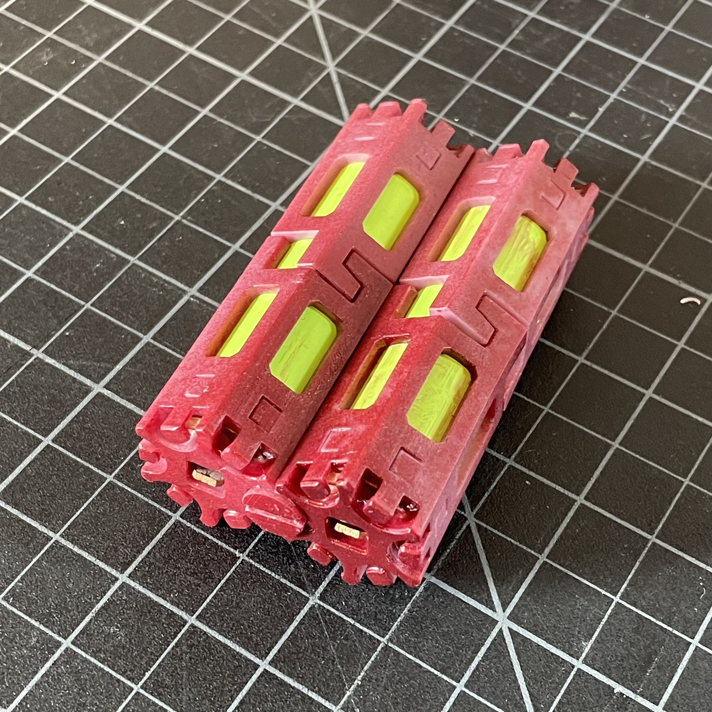
The Solution (so far):

The current Cell-Lock design uses a twisting connector to attach pairs of battery caps. These connectors are either entirely plastic to attach batteries without conducting electricity or include a copper pad on the bottom to form a solid electrical connection. Using a screwdriver to twist the connector 60 degrees engages the cam; locking the two caps together and creating a strong connection. Parallel and series cell groups can be attached and tested in this manner before continuing assembly. The cell caps on the positive and negative sides are held in place using M3 aluminum screws and 60mm standoffs or can simply be mounted directly into their enclosure.

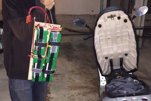
Batteries built using these connectors perform much better than any of my earlier prototypes, and I’m currently using a 36-volt battery to power my E-bike with no vibration or strength issues.

Notes and Improvements:

I’m still working on improving the design and assembly process for these parts, as my current method involves a lot of manual fussing around with the small copper parts that I use for the connectors. Currently, I use a resin printer to make the plastic components, and order my copper parts from SendCutSend, which are then shaped and attached using several custom jigs.

My goal is to allow anyone with a (dialed in) 3d printer to be able to make these for either 18650 or 21700 batteries, but I still need to simplify the build process somewhat before I publish the files and an assembly guide. This is still a work in progress, so let me know if you have any suggestions to make it better!

Cell-Lock Hex.step

step - 1.41 MB - 02/26/2026 at 19:11

Download

Cell Lock Square.step

step - 972.78 kB - 02/26/2026 at 19:11

Download

Cell-Lock Connector.step

step - 147.38 kB - 02/26/2026 at 19:11

Download

Copper Ring.step

step - 63.96 kB - 02/26/2026 at 19:11

Download

  • Upgrades people, Upgrades!

    Ben19 hours ago 0 comments

    During the course of some real-world testing (riding my bike around town), I ran into a fairly serious flaw with the current version of Cell Lock. I’ve been using a 36v 5Ah (10s2p) setup, connected to my motor controller through a Daly BMS as pictured below.  Most of the time this works great, delivering 20-30A peak at full load when I’m going uphill, and keeping the cell voltages from dropping too low. 

    36v Battery

    The problem with the current design only shows up when the ground gets bumpy: Currently, Cell-lock consists of two end caps attached to each individual battery. These end caps are joined to each other with locking connectors, and then secured to aluminum standoffs. For the cells in the middle of the battery, this is completely fine: each symmetrical pair of standoffs keeps the cap in line with the axis of the cell, and ensures the copper plate in the cap has good contact with the cell. This doesn’t work nearly as well for the cells on the edges of the battery: because the standoffs can only be attached on one side, the cap ends up at a slight angle to the battery. This doesn’t cause a problem during the initial assembly, but all it takes is a good jolt to briefly disconnect a cell. This in turn makes the BMS very unhappy, and it promptly cuts all power to the motor, often right at the steepest part of the hill. 

    Unequal forces caused by the standoffs

    The solution:

    I’m getting rid of the standoffs entirely. This will hopefully have the benefit of fixing the contact issue, and as a bonus, help to simplify battery assembly. The downside is that the caps now need to be significantly taller to snap together without any extra components. I’ve printed a few concept designs out, and they seem much better at withstanding external vibration, however I’m waiting on some new copper tabs to come in to fully rebuild the battery. I’ll upload the new design when I’m satisfied that it works better than what I’ve got now. Sorry Vittorio, the thermal testing will have to wait a bit!

View project log

Enjoy this project?

Share

Discussions

Vittorio Lumare wrote 02/27/2026 at 12:38 point

Hi, I am really excited by this solution, but I am worried about temperature. Lithium-ion batteries can go above 60C, what material do you suggest to use for printing? To prevent a meltdown and possible short with flames and explosion..

  Are you sure? yes | no

Ben wrote 02/27/2026 at 18:39 point

Hi Vittorio, unfortunately the short answer is that I don't have a good idea of the thermal limits yet. I've printed all the parts using ABS-like resin, but the manufacturer doesn't list the melting temperature in the datasheet. Similar resins have melting points above 100 C, but I'm a little wary. 

So far I've only pushed 10 amps continuous at 40v which wasn't enough to really get hot. I'm currently setting up a testing rig on the bench to get a good idea of the amp and temperature limits before I start making more of these. I'm hoping that the little copper connectors will act as fusible links and protect the battery from a short, but I'll need to do real testing to make sure. With any luck I'll be able to give you a better answer in a week or two :).

  Are you sure? yes | no

Vittorio Lumare wrote 02/27/2026 at 20:10 point

Hi Ben, I get, you need to test. A fuse will surely protect against surges and extreme heat. Anyway, I also suggest to test the deformation caused by prolonged usage at medium temperatures, a thing which could cause shorts at some point (if deformation progresses much) without blowing up the fuse : these can be more difficult to prevent.

I am looking forward to see your testing results! :-)

  Are you sure? yes | no

Similar Projects

Does this project spark your interest?

Become a member to follow this project and never miss any updates