Well now, we have an ebay-ish pogo pins, but need the "other side" of the electrical contact. I was thinking, I will make a simple, two sided PCB. On the "upper" side, there would be the EEPROM, and on the lower side, I will put huge pads for the contacts. I looked around, and found out, that the OSHPark is making PCB-s with ENIG. I hope it will be sufficiently resistant.
Until this project, I was working in Eagle. But for a while, I was thinking of learning KiCAD. Well, there won't be better time for it, to start learning. So, I am trying to make the PCB in KiCAD.
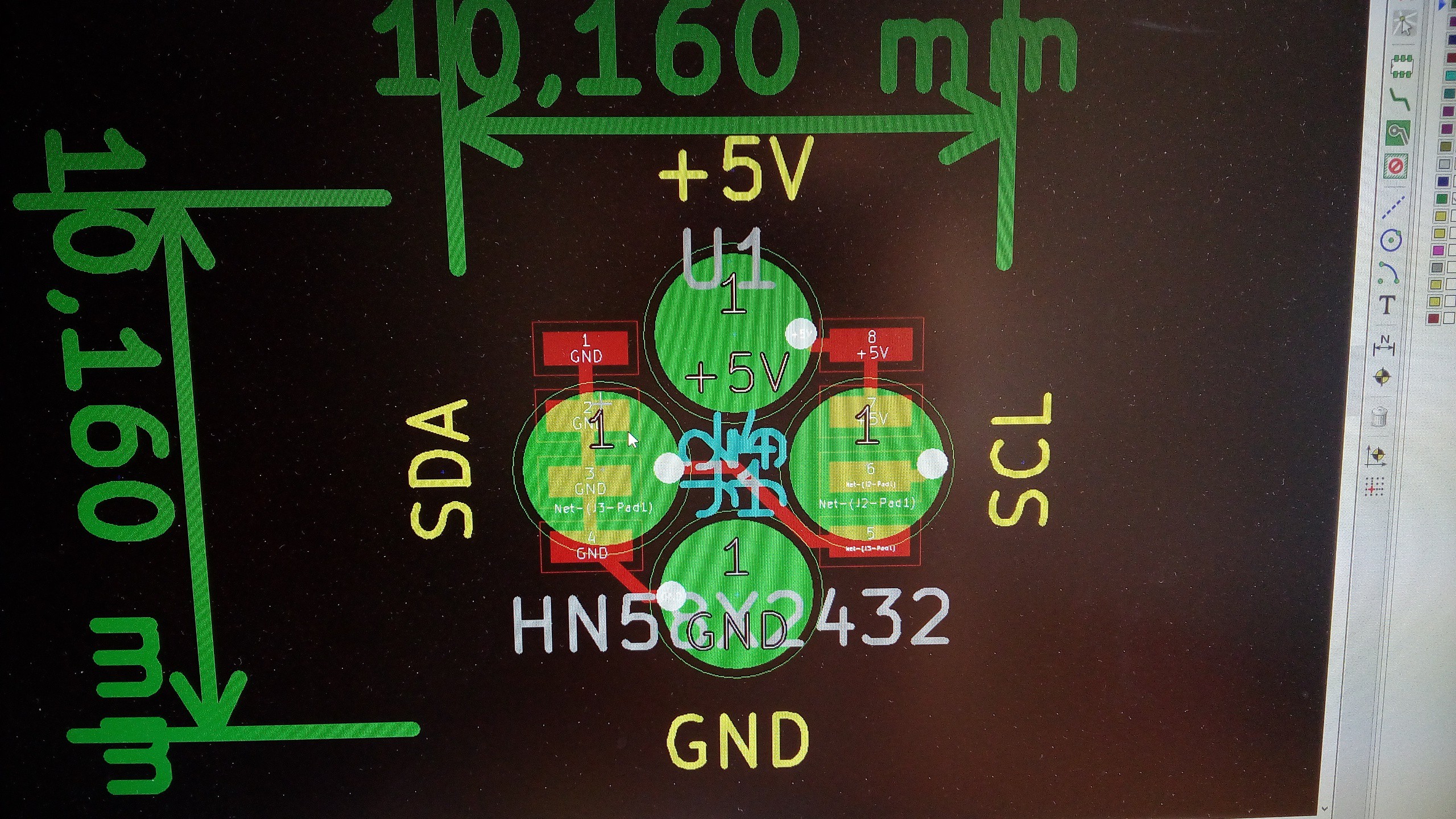
I just sourced some Hitachi HN58X2432FP EEPROMs for 0.1$ per piece (4k x 8 bit), in 8 pin SOP package. I think its capacity is fairly enough :) This component isn't in the KiCAD's library, so I started with making it. Took some other SOP-8 package EEPROM, changed the relevant informations, rearranged a little the schematics pinout, to have my schematics look better. Made the board. I was calculating, that I need to have it somewhere in the 1x1cm size (in imperial it is PI/8 inch :) Ok, so I will panelize it, and cut it to the size. How will I cut it out to this size? Well, just like how I will panelize it in KiCAD: at the moment, I haven't the slightest clue. But I do have a picture of the board:
Discussions
Become a Hackaday.io Member
Create an account to leave a comment. Already have an account? Log In.