 pchala
It’s time to dive into the hardware and software that actually makes the pressure profiling possible. Controlling a vibratory water pump requires precise AC phase control. To do this, we need to detect the exact moment the AC waveform crosses zero volts, and then wait a calculated number of microseconds before firing a Triac.
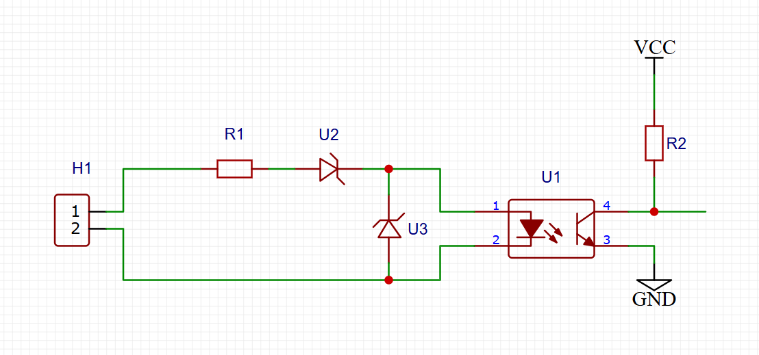
Here is the schematic I am using for the zero-cross detection and Triac firing circuit:
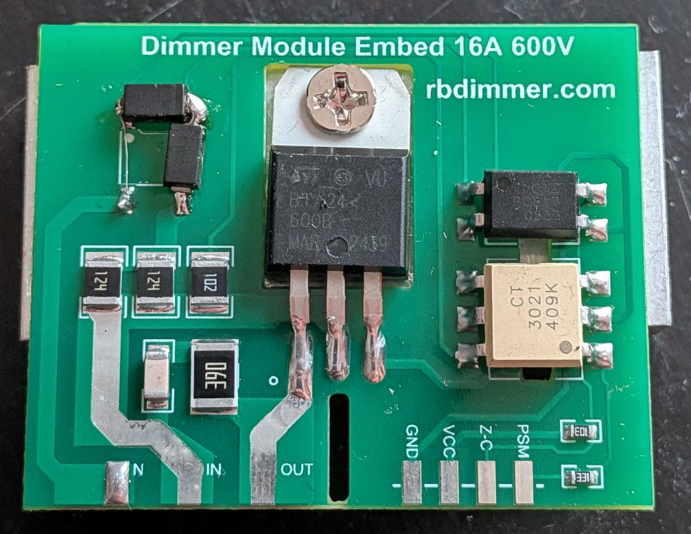
And here is how the modified board turned out:
Testing the Control Loop
Before hooking the system up to high-pressure boiling water, I needed to verify the control loop. I set up a mock environment using a potentiometer to simulate the analog pressure transducer.
As I twist the knob to create an artificial pressure "error," the PID controller instantly recalculates and adjusts the AC phase delay to compensate. Here is the bring-up video showing the dual-PIO system running flawlessly and maintaining stable control:
The Secret Sauce: RP2040 Programmable I/O (PIO)
Doing microsecond-accurate AC phase chopping on a main CPU is a nightmare—if the CPU gets distracted by Wi-Fi or UI tasks, the pump stutters. To solve this, I completely offloaded the timing to the RP2040's hardware PIO blocks.
PIO Block 1: The Wave Measurer The first state machine measures the exact length of the AC half-wave in microseconds and pushes that data to the CPU to trigger the PID calculation.
        "wait 1 pin 0", // Wait for pin to go high
        "wait 0 pin 0", // Wait for pin to go low (detect falling edge of zero-cross)
        "mov x, !null", // Initialize X counter to 0xFFFFFFFF
        "low_loop:",
        "jmp pin, rising_edge", // If pin goes high, we found the next edge
        "jmp x--, low_loop",    // Decrement X and loop
        "rising_edge:",
        "mov isr, !x",  // ISR = NOT(X) = elapsed cycles
        "push noblock", // Push the period measurement to the RX FIFO
PIO Block 2: The Triac Trigger
The second state machine pulls the calculated microsecond delay from the PID controller, waits for the zero-cross, and fires the Triac at the perfect moment.
        "pull block",   // Pull phase delay from TX FIFO (block if empty)
        "mov x, osr",   // Move delay value to X counter
        "wait 1 pin 0", // Wait for Zero-Cross signal high
        "wait 0 pin 0", // Wait for Zero-Cross signal low (start of half-wave)
        "lp:",
        "jmp x-- lp",       // Wait for 'X' microseconds
        "set pins, 1 [30]", // Trigger Triac (pulse high for ~30 cycles)
        "set pins, 0",      // Set Triac gate low
PIO Block 3: High-Resolution Flow Measurement
I dedicated another PIO block entirely to the Hall-effect flow meter. This PIO block precisely measures time between signal edges and pushes them to FIFO. This gives the MCU incredibly high-resolution instantaneous flow rate (ml/s) and total volume readings.
        // --- 1. MEASURE HIGH STATE ---
        "mov x, !null",
        "high_loop:",
        "jmp x-- next_high", // 1 cycle
        "next_high:",
        "jmp pin high_loop", // 1 cycle
        "mov isr, !x",       // Pin went LOW, invert X
        "push noblock",      // Push HIGH duration
        // --- 2. MEASURE LOW STATE ---
        "mov x, !null",
        "low_loop:",
        "jmp pin low_done", // 1 cycle: breaks out if pin goes HIGH
        "jmp x-- low_loop", // 1 cycle: decrements and loops if X != 0
        "jmp low_loop",     // catch the fall-through and loop back
        "low_done:",
        "mov isr, !x",
        "push noblock",
Next step is to connect pressure transducer and adjust PID coefficients. Stay tuned!
Discussions
Become a Hackaday.io Member
Create an account to leave a comment. Already have an account? Log In.