 Jeroen Brinkman
How It Works: The Full Stack
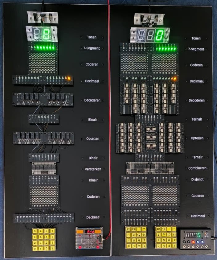
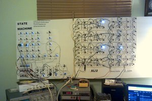
The project is organized into a vertical flow, making it easy to trace the signal from input to result:
- Invoeren (Input): Two keyboards allow you to select two numbers between 0 and 7.
- Decimaal (Decimal Indicator): Yellow LEDs provide immediate feedback on which decimal numbers were selected.
- Coderen (Binary Encoding): A diode matrix converts the decimal input into 3-bit binary signals.
- Binair (Binary State): Red LEDs display the "raw" binary bits before they enter the arithmetic unit.
- Versterken (Amplification): To ensure the logic signals have enough "oomph" to drive the subsequent stages, a ULQ2003 amplifier works alongside power relays to boost the signal.
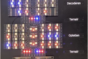
- Optellen (The Adder): This is the heart of the machine. It uses one half-adder (for bit 0) and two full-adders (for bits 1 and 2) constructed from Omron G5V-2 relays. This stage calculates the sum and manages the carry-out bits.
- Decoderen (Binary-to-Decimal): A relay-based demultiplexer takes the binary sum (which can now be as high as 14) and converts it back into a decimal signal.
- 7-Segment Encoding: A final diode matrix maps the decimal result to the specific segments (a-g) of the output display.
- Tonen (The Result): A large 7-segment display reveals the final sum.
How the binary adder works
The diagram shows a 1‑bit full binary adder, which adds two binary inputs (a and b) together with an incoming carry (Cin). The circuit produces two outputs: the sum bit (C) and the carry‑out (Cout).
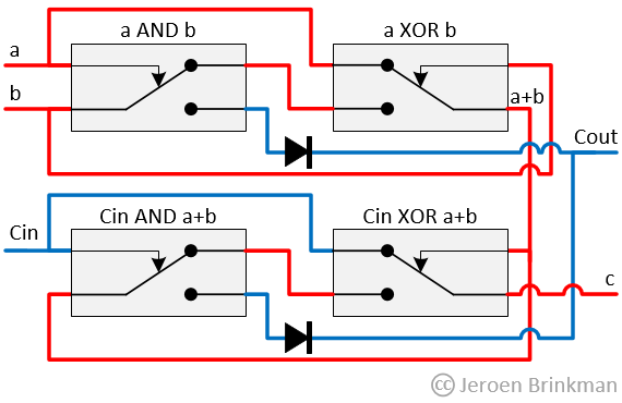
First, the inputs a and b are combined using both an XOR and an AND operation. The XOR gate generates the preliminary sum (a ⊕ b), while the AND gate generates a carry if both inputs are high (a ∧ b).
Next, the incoming carry (Cin) is added to this preliminary sum. Again, an XOR operation produces the final sum bit (C), and an AND operation detects whether this second addition generates a carry.
Finally, the two possible carry signals are combined to form the output carry (Cout). This means Cout goes high if either:
- a and b are both high, or
- Cin is high while a ⊕ b is high
In logical terms:
- C = a ⊕ b ⊕ Cin
- Cout = (a ∧ b) ∨ (Cin ∧ (a ⊕ b))
By cascading multiple identical stages, this 1‑bit adder can be extended to form a multi‑bit binary adder.
Technical Highlights
- Relay Logic: The arithmetic is performed using classic relay logic, where two half-adders are combined to create a full-adder.
- Diode Matrices: Rather than using integrated circuits, the "programming" for the 7-segment display and the decimal-to-binary conversion is handled by large, visible diode grids.
- The "Clack" Factor: Every calculation is accompanied by the rhythmic sound of mechanical switching, turning math into a tactile experience.
Why Build This?
It’s designed to pull back the curtain on digital computation. By separating the encoding, arithmetic, and decoding into distinct, LED-monitored layers, it becomes a powerful educational tool for anyone wanting to understand how computers actually compute at the most basic level.
This project is part of my four‑project series “My Relay ADDiction” (pun intended): a hands‑on exploration of logic and arithmetic built with relays, diodes, LEDs, and a healthy amount of curiosity.
Each project stands on its own, but together they form a learning path—from basic binary gate behavior (It’s logic!), through number representation (TritBits), to full adders in both binary and balanced ternary.
Related projects in the series:
• It’s logic! – https://hackaday.io/project/184752
• Visual Binary Adder – https://hackaday.io/project/205210
• TritBits – https://hackaday.io/project/205130
• Balanced Ternary Relay Adder – https://hackaday.io/project/205212
 Dr. Cockroach
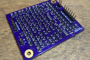
 Eric Ljungquist