 Tony Goacher
I planned to create a steering system with DIY forks at a rakish angle giving that Easy Rider look.
The TrakTrike is designed to come apart for easy transport so I need the forks and wheel to be detachable. I bought a used 'Fat Tyre' bike front wheel with a quick release from ebay and set about designing forks around it.
I started on the steerer tube. This is the tube which connects to the frame and the steering column rotates around inside.
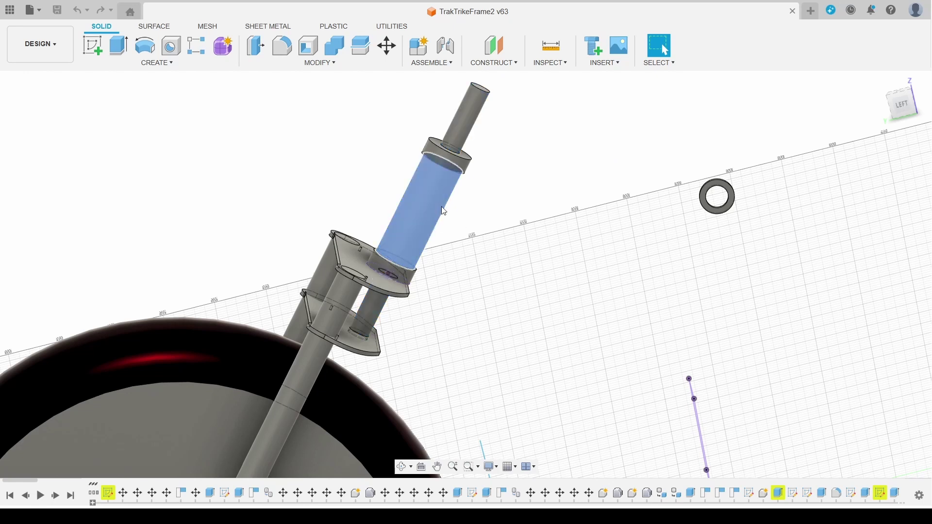
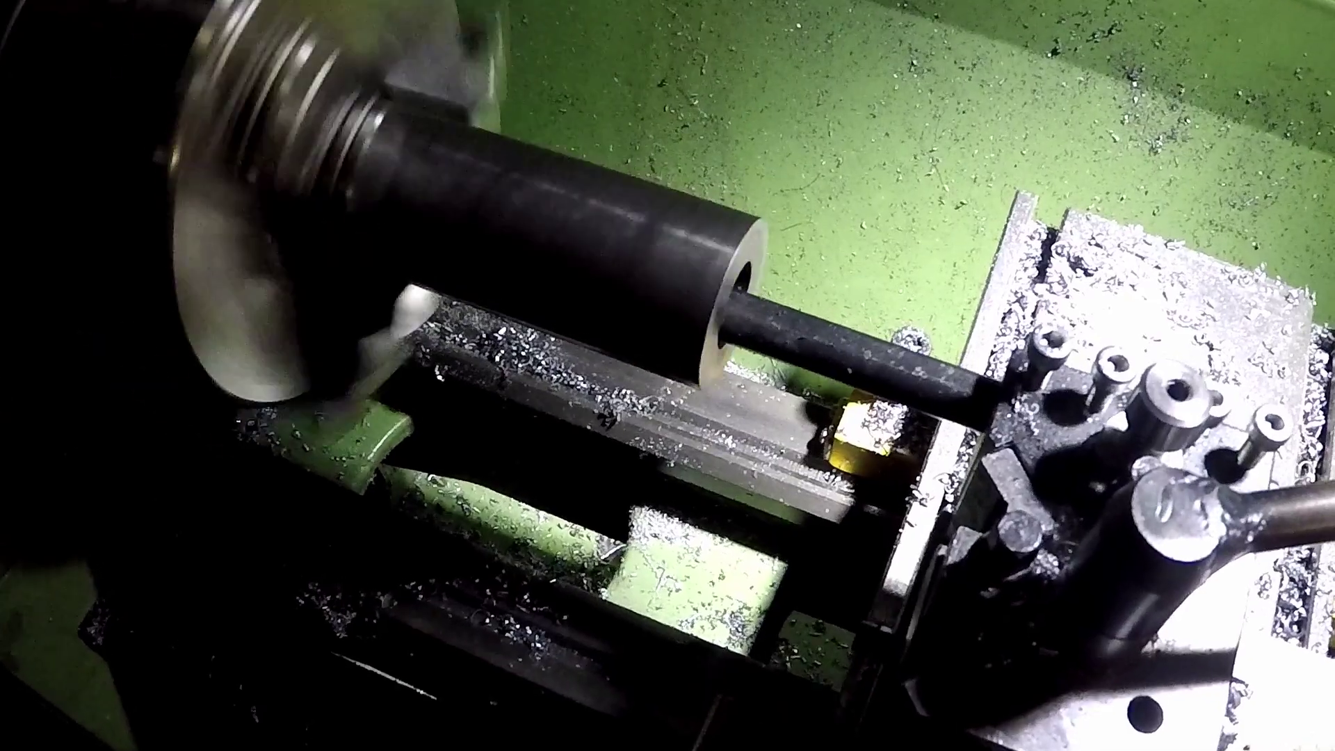
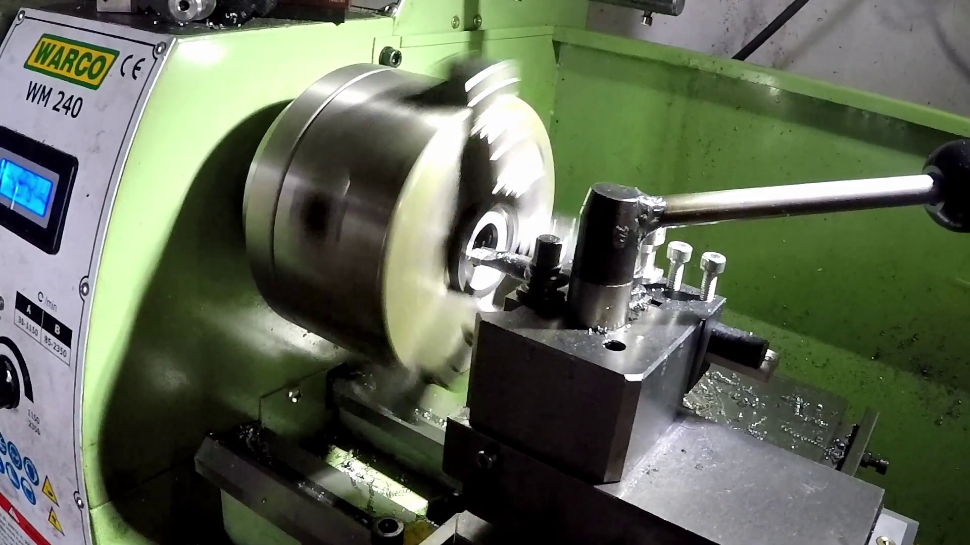
The actual steering column has a diameter of 20mm and rotates on thrust bearings at the top and bottom of the steerer tube. I started by boring the steerer tube on the lathe.
Then I created some disks hold the thrust bearing housing washers.
Here's the steerer parts ready for assembly.
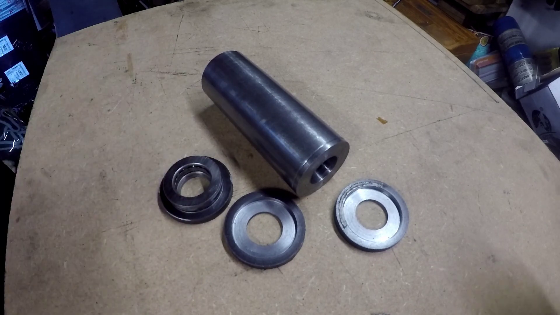
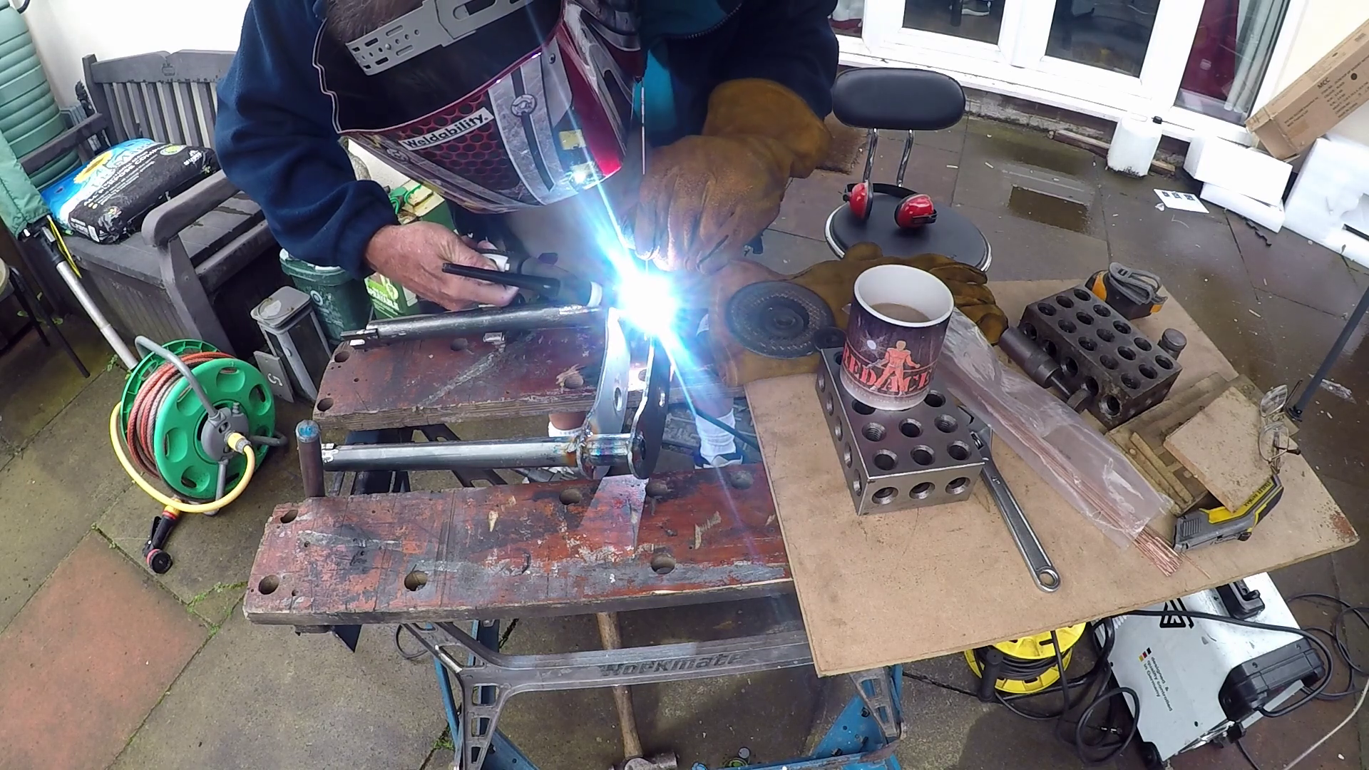
I used a piece of 20mm bar to align everything, then welded the bearing housing plates into position.
After measuring the fat tyre I designed some fork yokes. The fork legs are made from the same 26mm tube as the frame with the fork ends cut from 6mm steel plate welded into the ends of these tubes and a slot cut in to take the wheel axle.
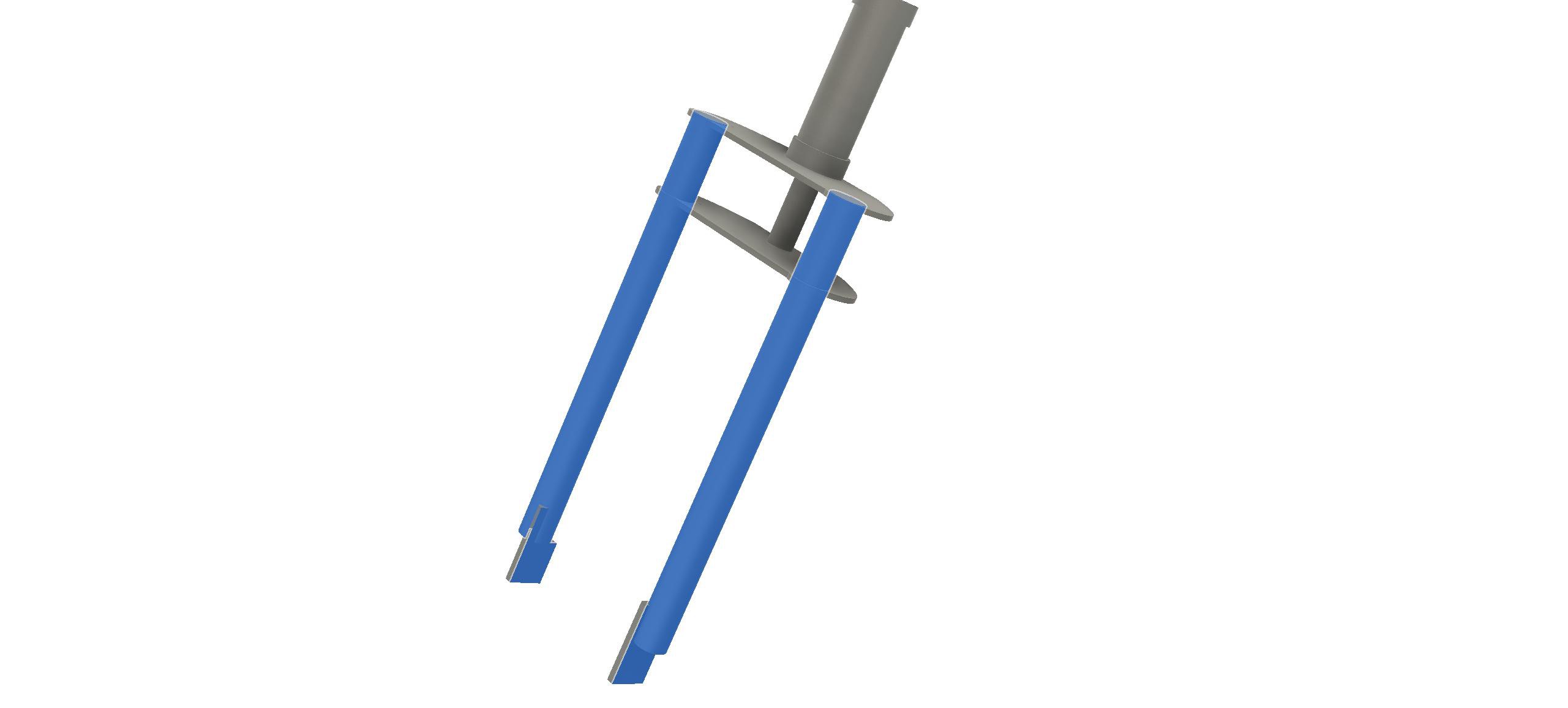
To make sure everything lined up before I committed to expensive steel I 3d printed the fork and laser cut the yolks from MDF.
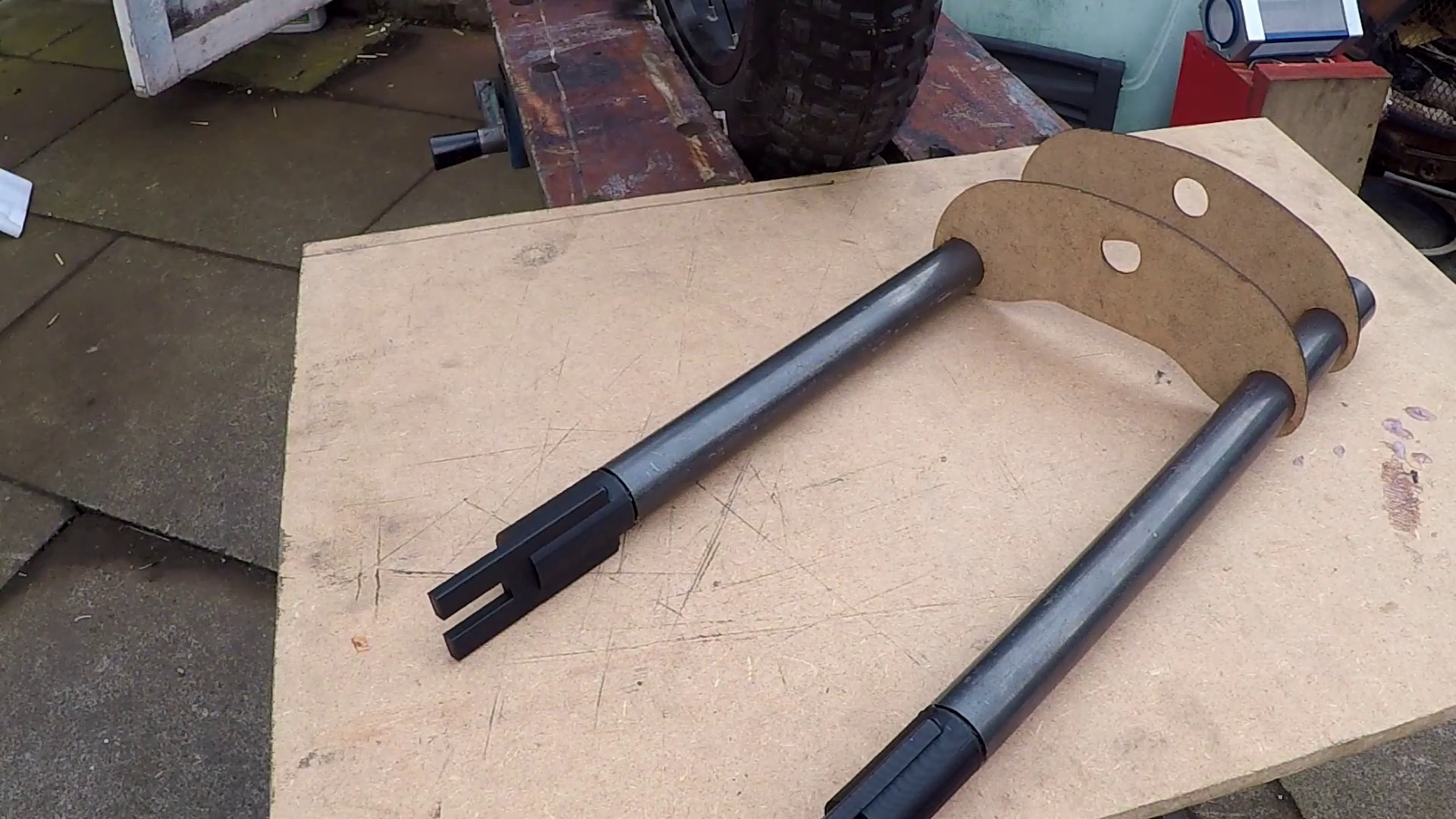
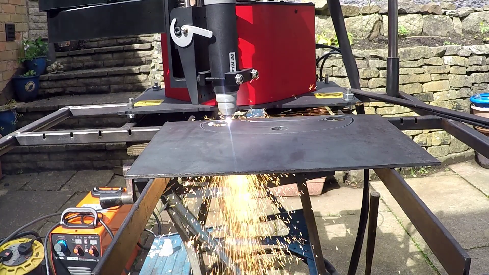
It's a good job I did because the forks were about 10mm too wide. I redesigned the yolks and plasma cut them on the ArcDroid.
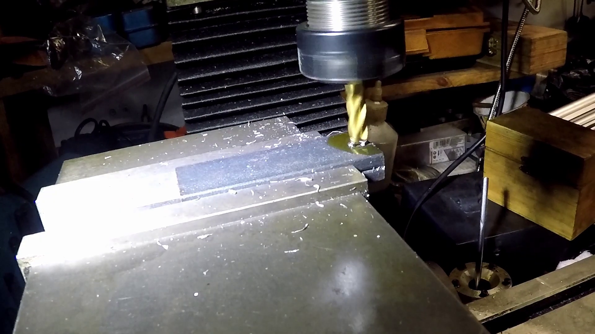
The fork ends had the wheel axle slots milled...
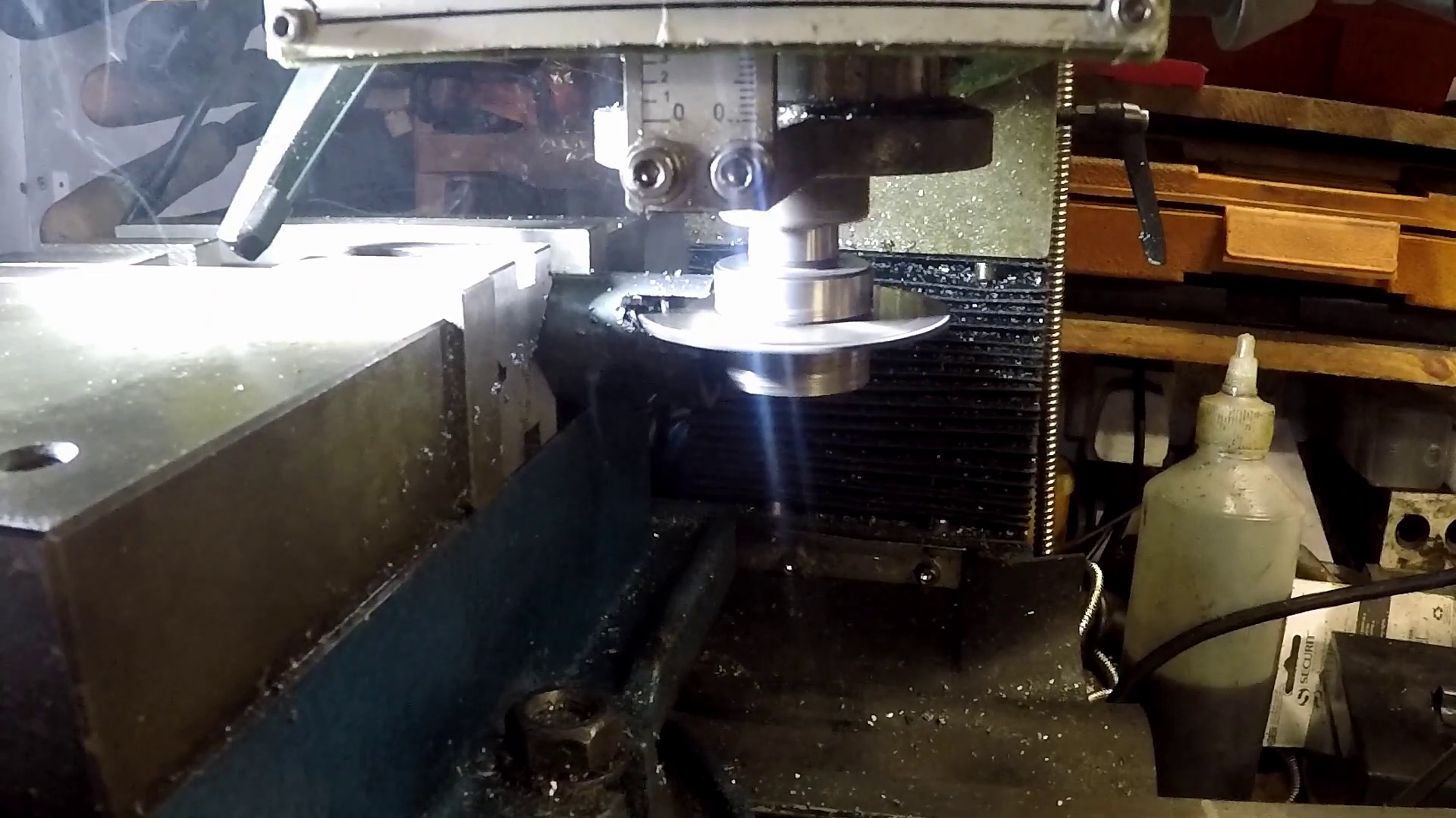
The ends fit into slots cut into the fork leg ends. These were created with a slitting saw.
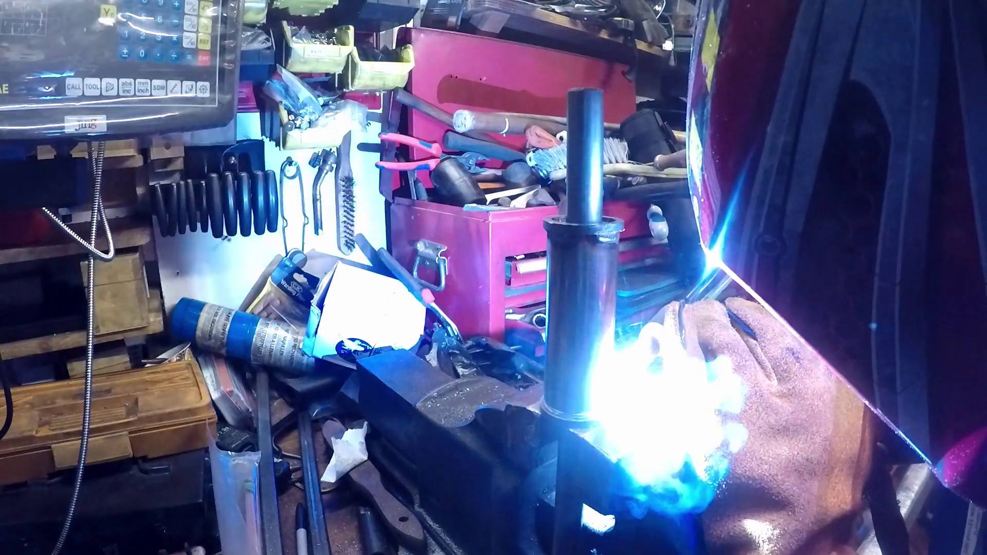
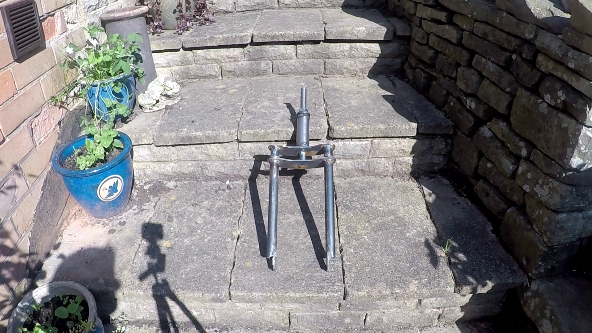
And everything welded together..
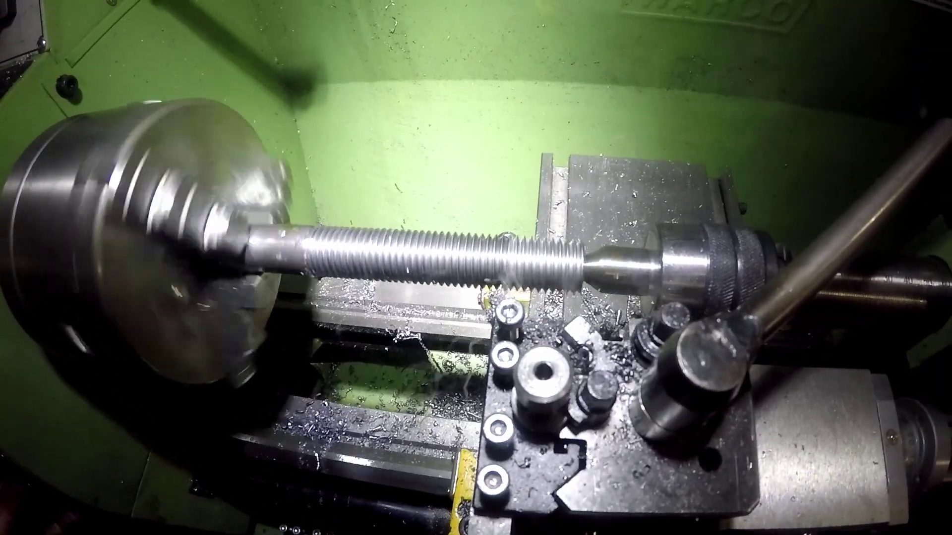
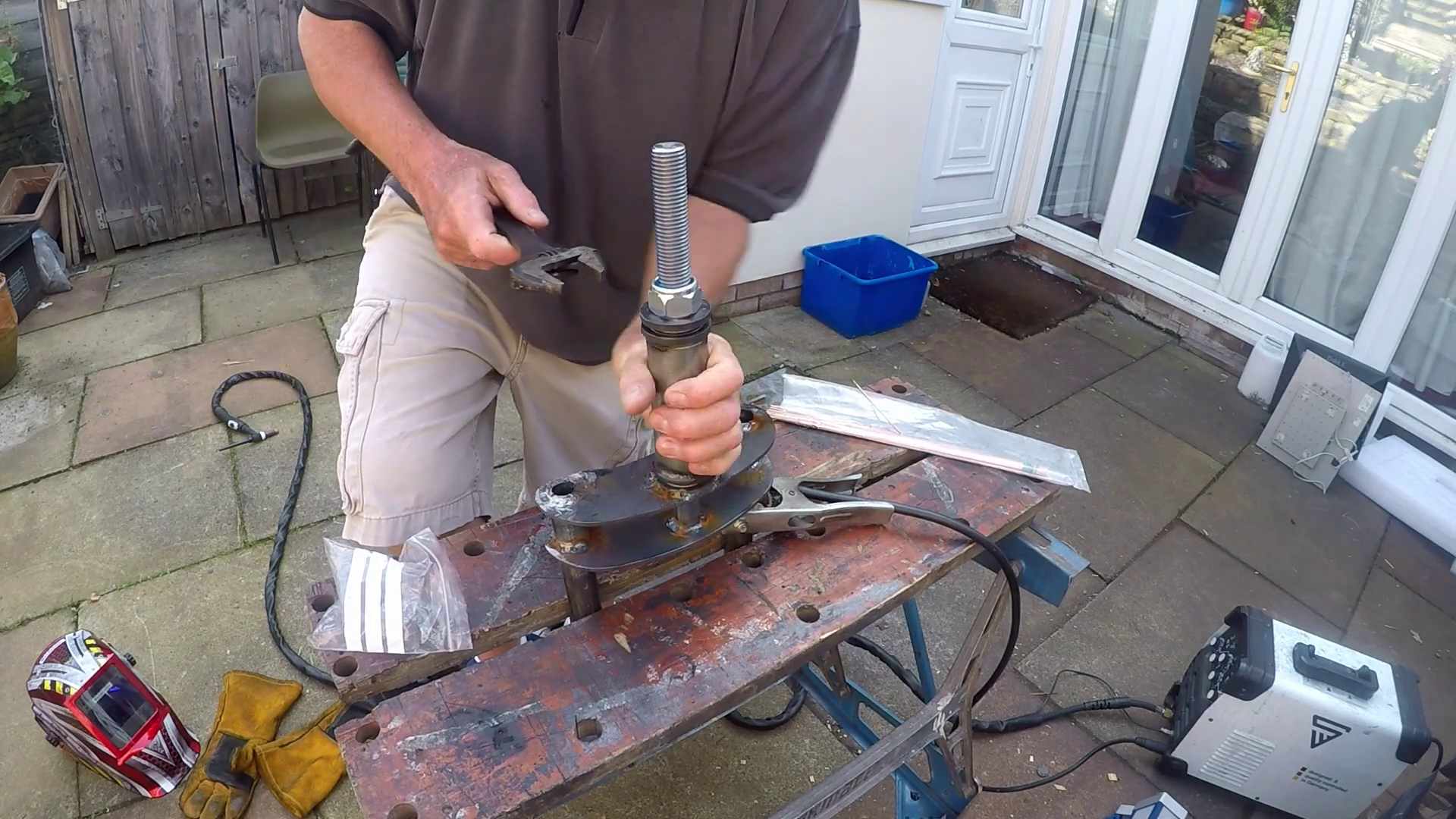
I single point threaded the steering column, a locking nut on here will clamp the thrust bearings together.
Doesn't look too bad for home made....
Two bent plates welded to the frame serve as a mount for the forks.
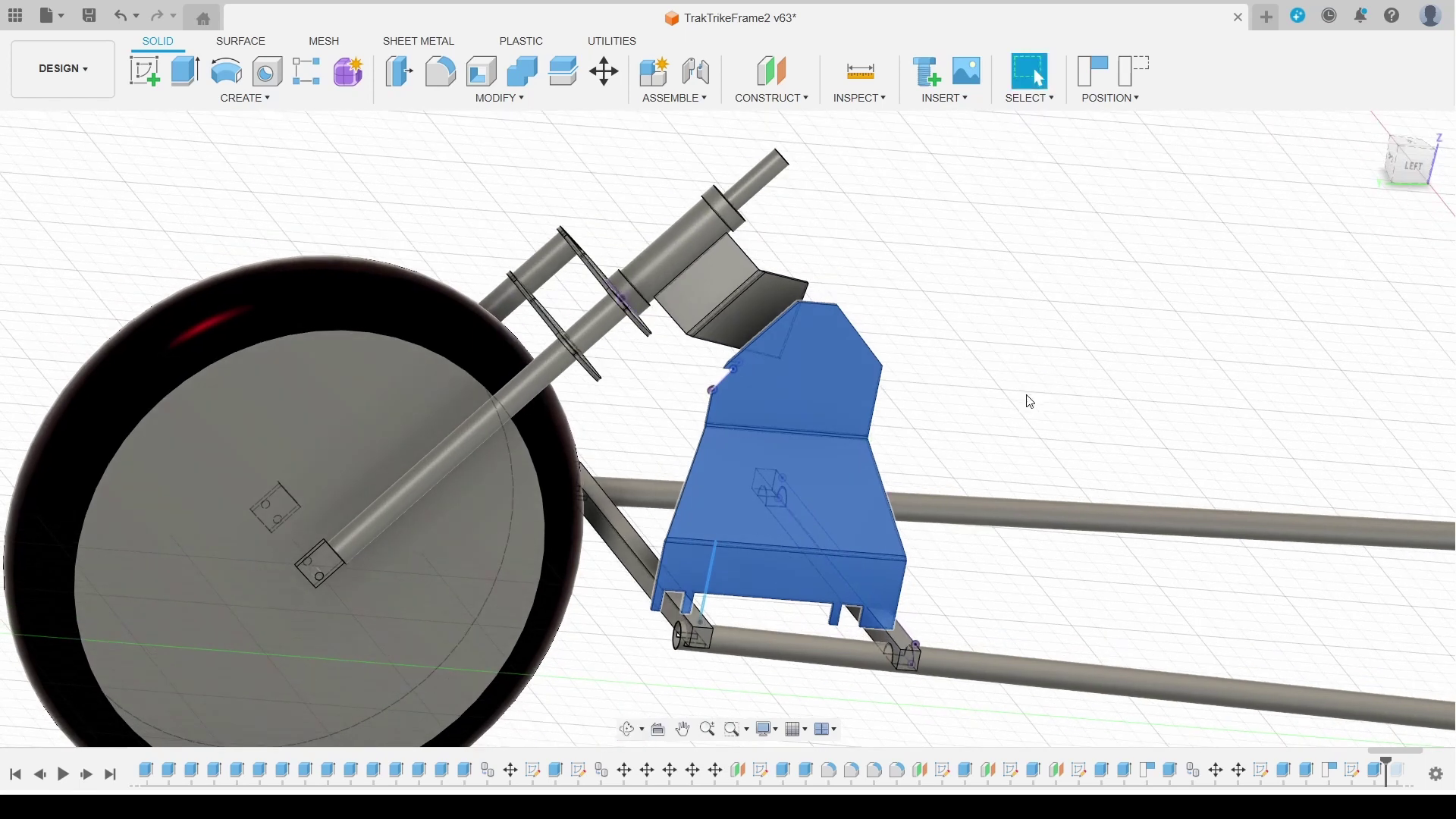
A second set of plates welded to the steerer fasten the forks to the plate with 3 M8 bolts on each side
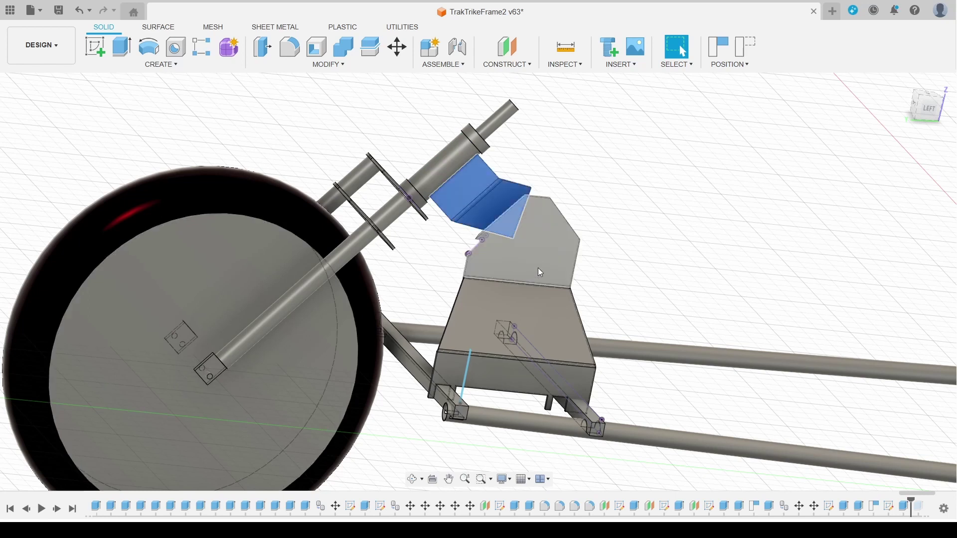
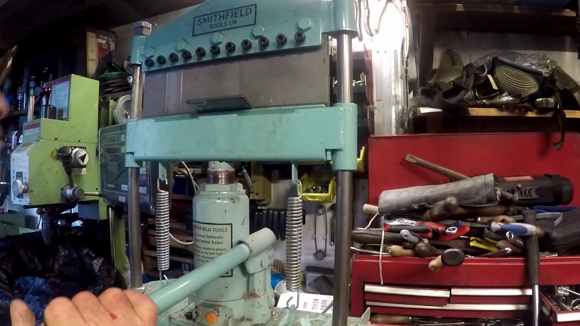
Bending these plates proved problematic. At 5mm and quite wide they presented a challenge to my small hydraulic press. In the end I used the plasma cutter to cut the blanks out and also used it to 'score' a line along the bend.
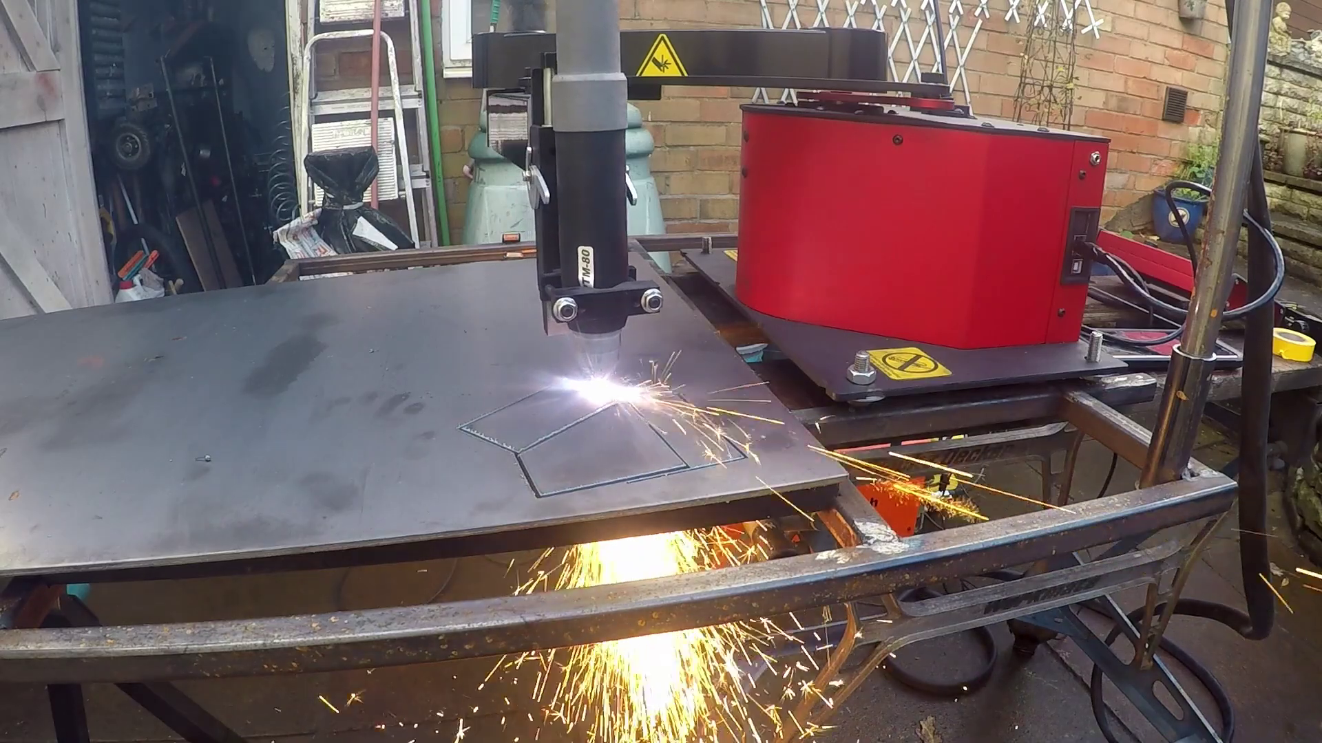
This thinned the metal sufficiently to bend it. I simply welded the seam up after the bend. The mounting plates on the frame were done in the same way. I documented this process in morer detail here.
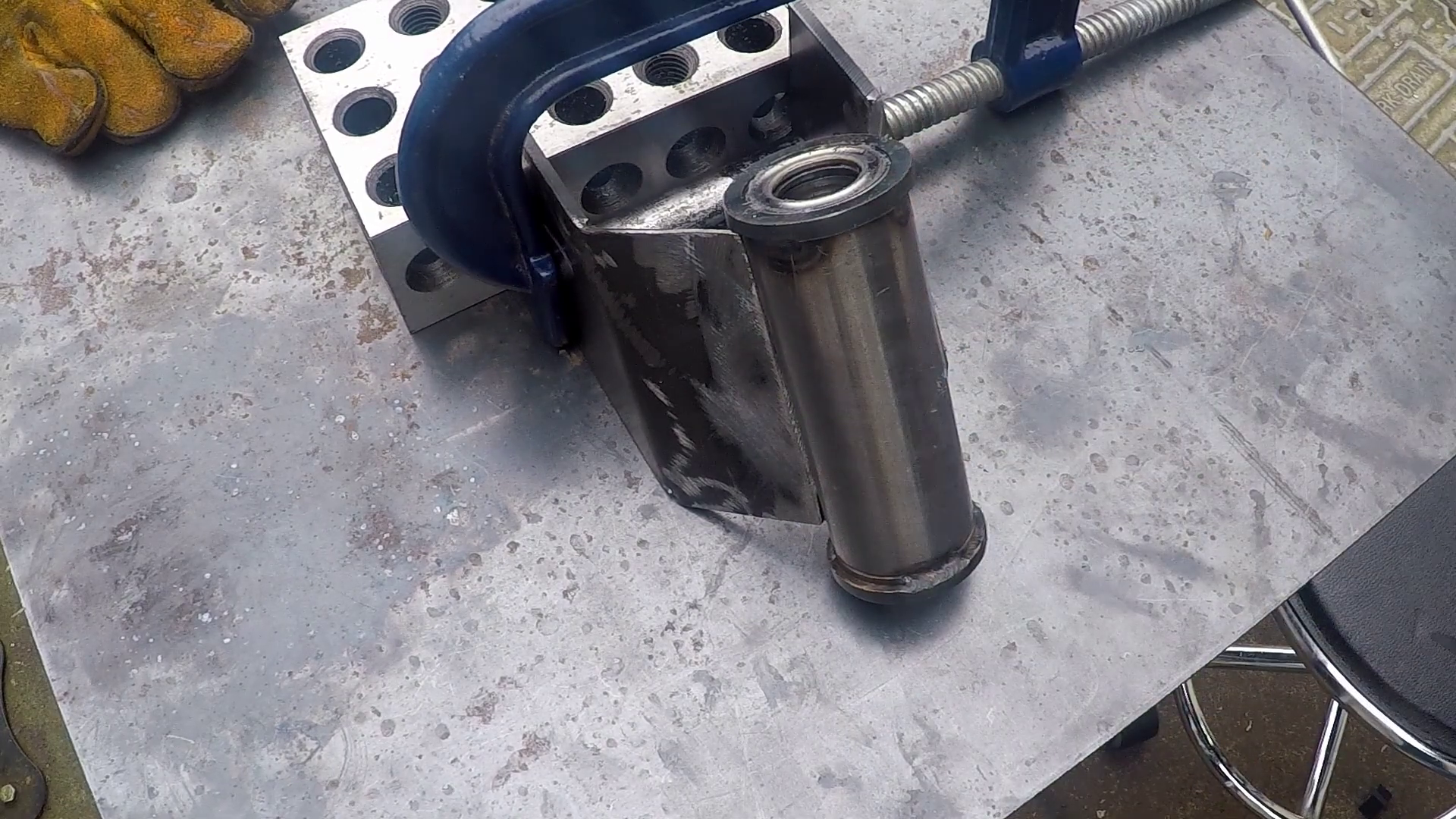
I ground a bevel on the angle plates to improve contact with the steerer tube. Then the tube and the plates were welded together.
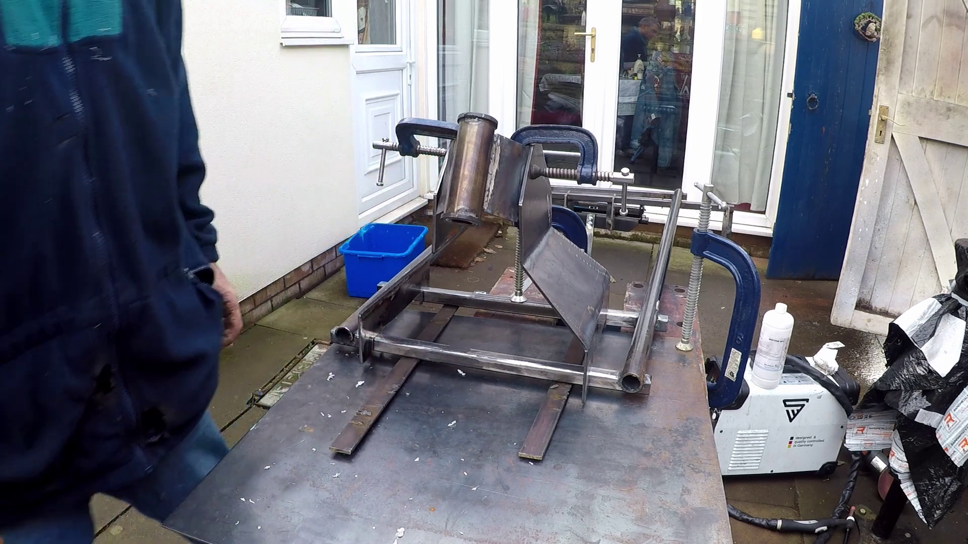
I then clamped the fork mount plates to the frame plates, adjusting them until I was happy and positioning the frame plates onto the frame for a check before welding to the frame.
With the frame plates fitted I used a paper template, spray glued to the fork steering plates to align holes to be drilled through both the frame and the steering plates.
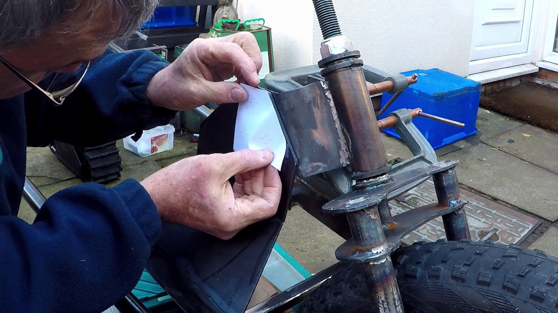
With the holes drilled on one side I could bolt it up and drill the other.
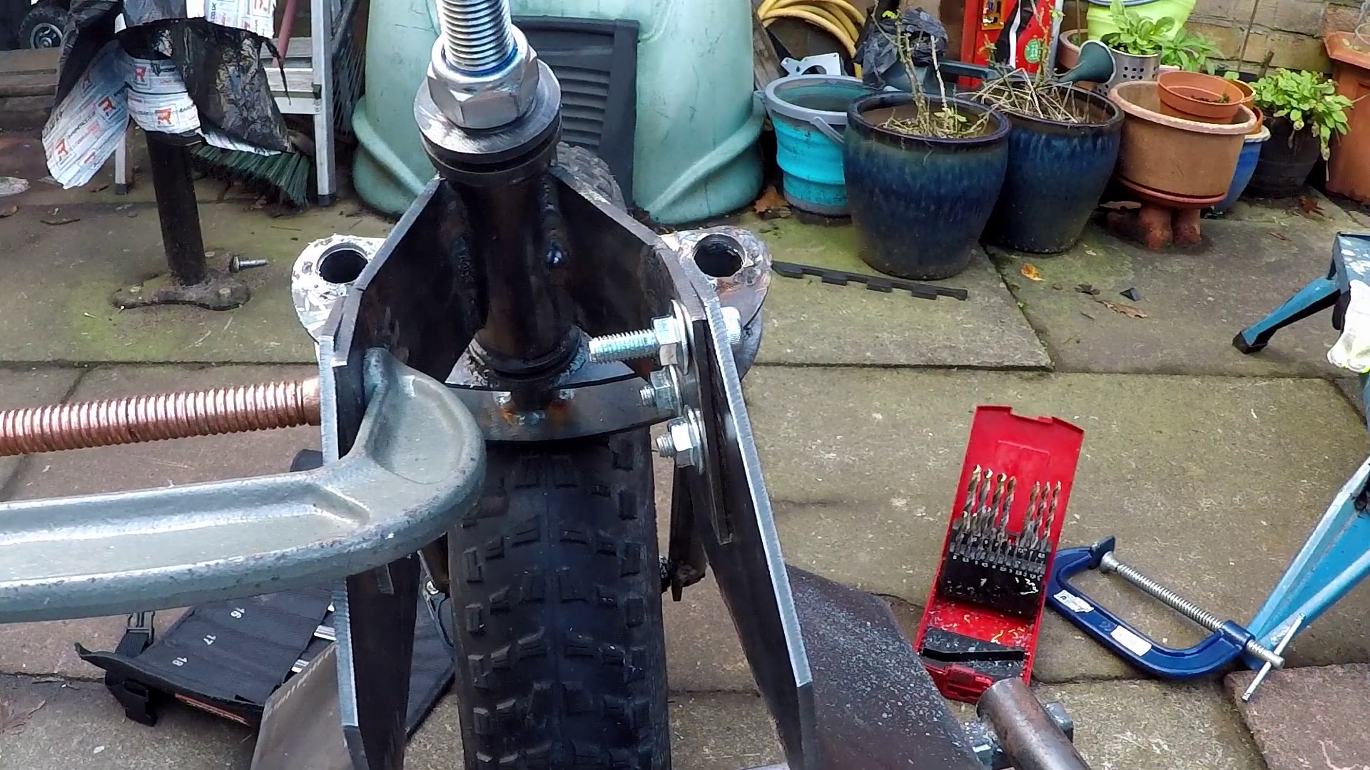
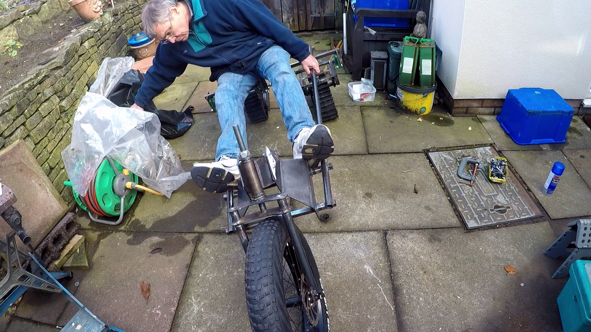
With both sides of the forks bolted to the frame I could now sit on it and give it a try! I chose to ignore how it leaned over. I will regret this later.....
Discussions
Become a Hackaday.io Member
Create an account to leave a comment. Already have an account? Log In.