 Tony Goacher
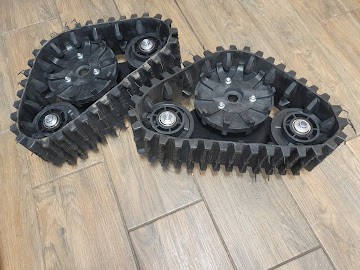
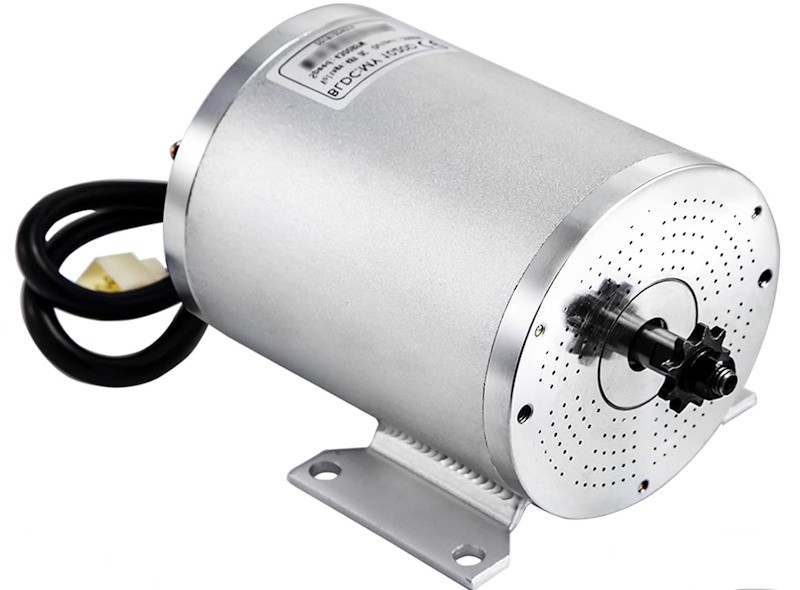
Before I could do anything, I needed to know if I could actually get tracks to move under electric power. So off to Aliexpress and I bought a 2kW brushless motor and controller, and some snowblower tracks.
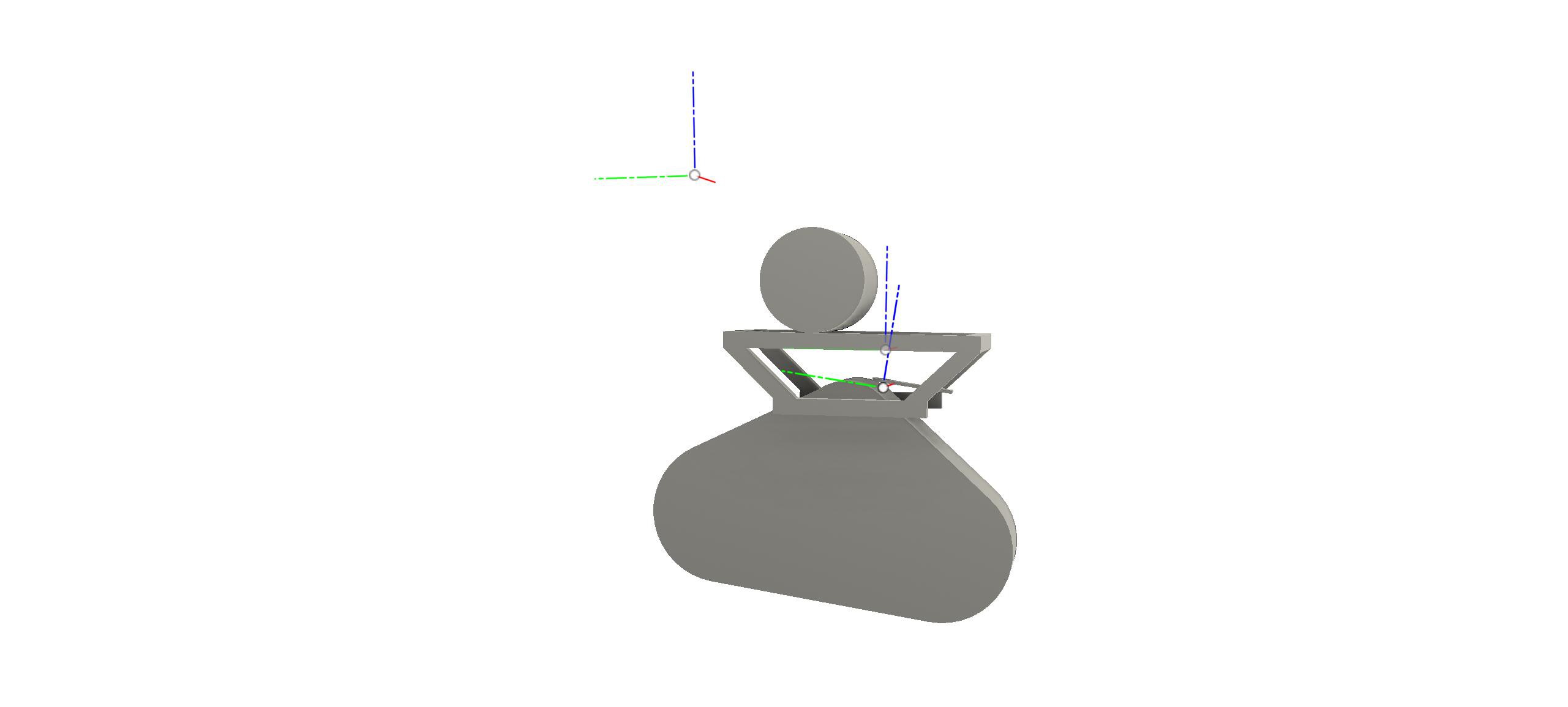
I created a CAD model of what I thought would be an acceptable mount for the tracks in Fusion360:
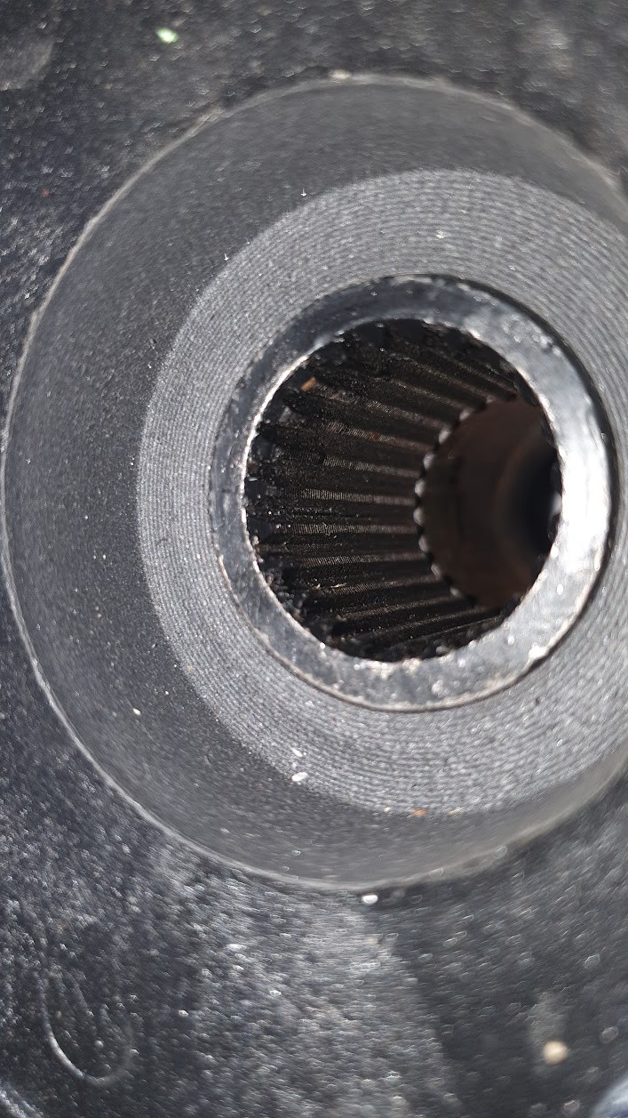
The tracks require a splined drive shaft and this is a custom build I was going to have to make my own. With the correct drive shaft dimensions, I started to consider how I might make the shaft. Without this, the project was dead.
The only way I could cut splines like this was on the mill. I have a Vertex rotary table and this seemed the best route thoughI had no experience of using it. Having some embedded software experience I created the 'Rotary Table Buddy' which allows me to drive the table electronically..I just tell it how many splines I need. This was a project in itself and is documented here.
Using the RTB, I first created a test piece in Delrin. This fitted the track splines perfectly. I turned a drive shaft on the lathe, then transferred it to my small mill and proceeded to cut the splines. Each spline took about 15 mins to cut with a triangular profile cutter as I had to reduce the depth of cut as the spline became deeper and wider.
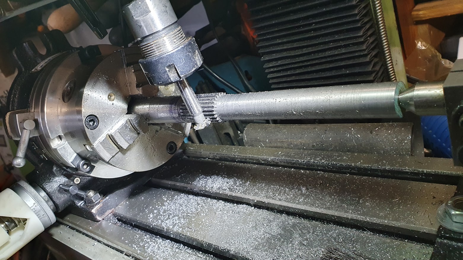
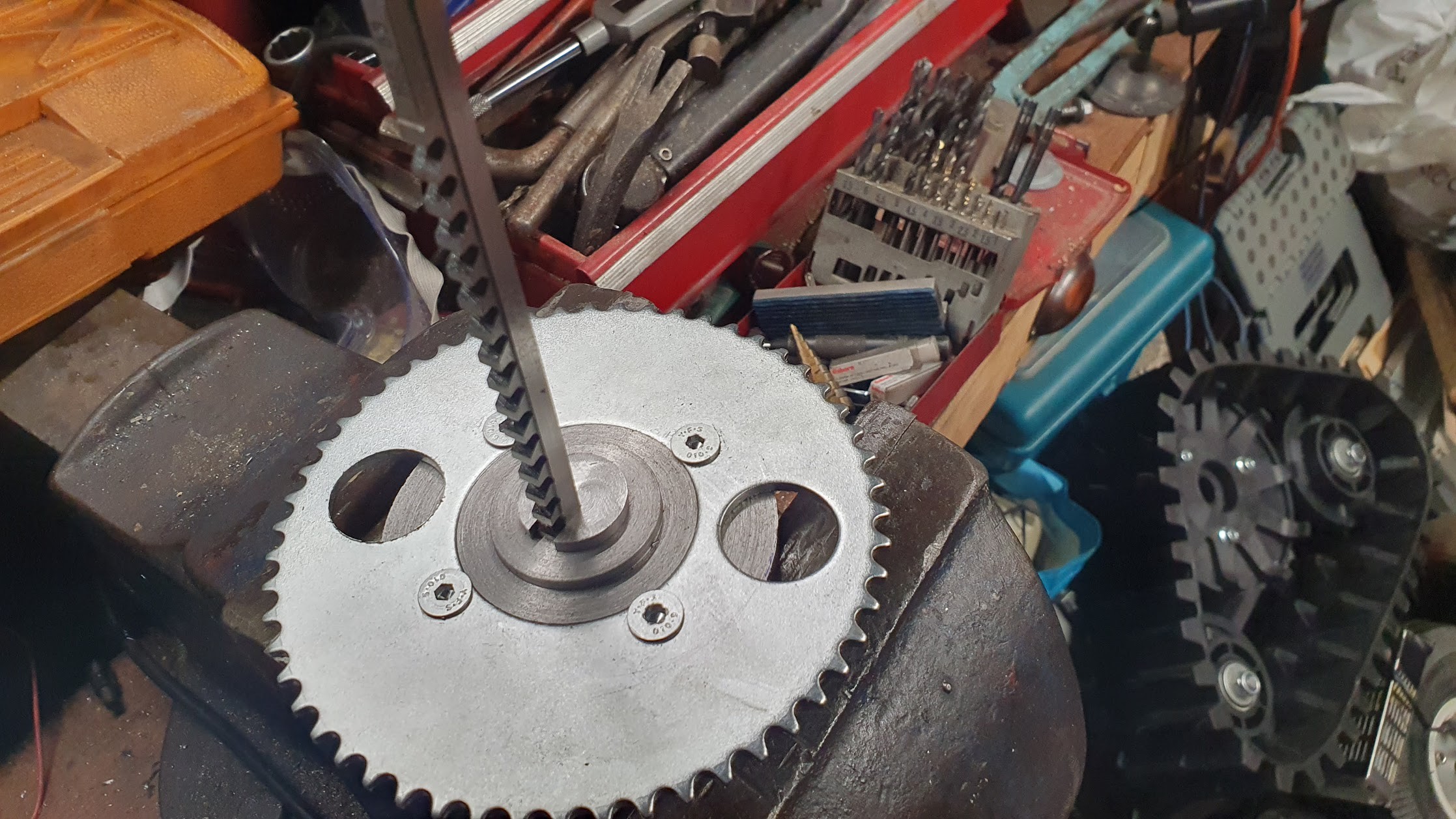
The drive shaft was to be mounted on 20mm pillow block bearings with a sprocket from a 50cc moped attached to the drive shaft and chain driven. I created an adapter plate to connect the sproce to the shaft using a keyway which I cut with a broaching bar.
The motor mount frame was created from welded 20mm box section steel. I also created a motor mounting plate with mounting slots that allowed the motor to be adjusted in x and y allowing for sprocket alignment and chain tightening.
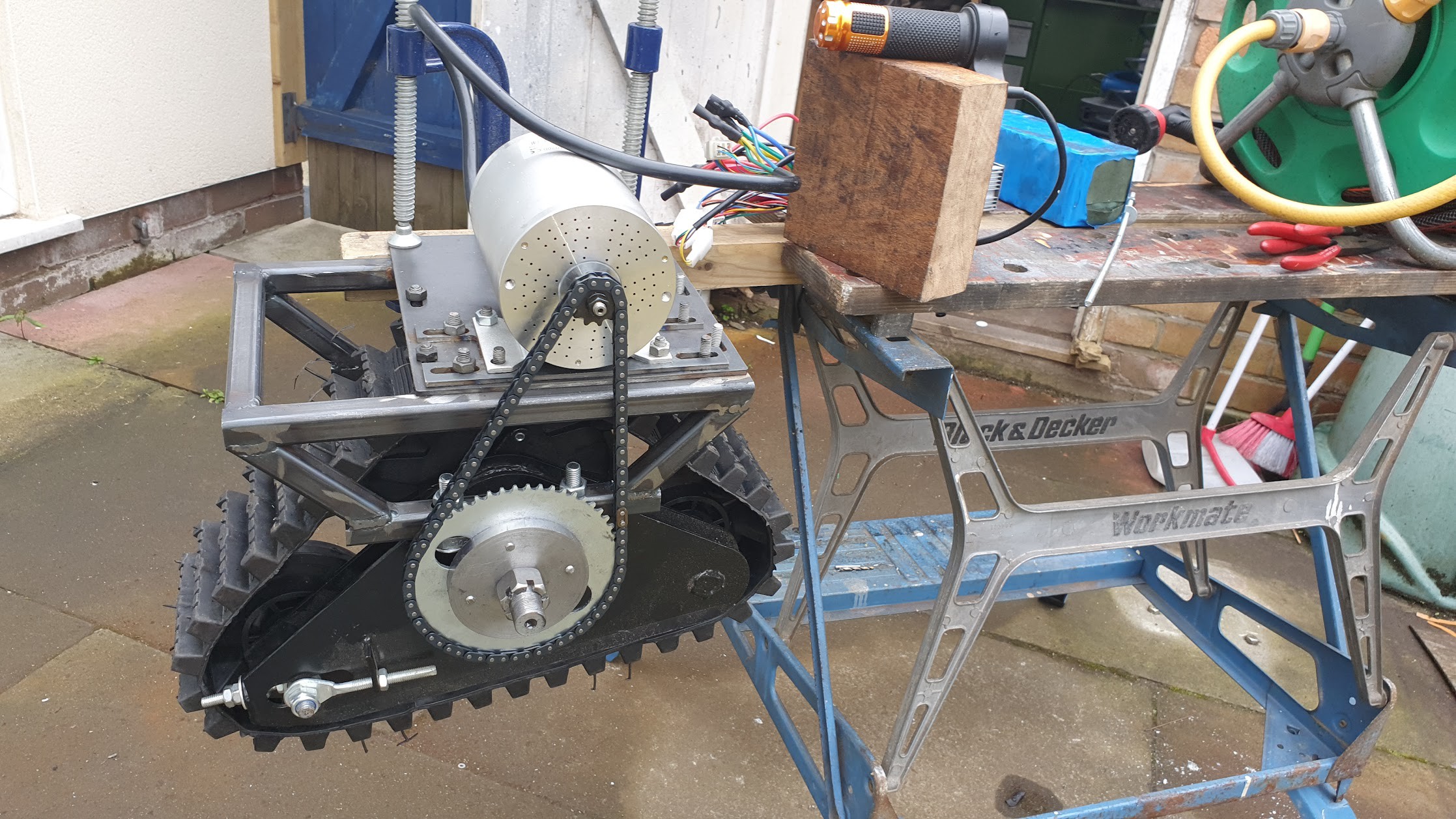
I stole the battery from my son's e-scooter for the first test with everthing in place.
There's a video blog of the track units here
Discussions
Become a Hackaday.io Member
Create an account to leave a comment. Already have an account? Log In.