Close
0%
0%

ESP32 SMD Rework Station with PID and Micropython

ESP32-based hot air SMD rework station with PID control, dual PCB design, built-in safety and calibration features.

Similar projects worth following
75 views
0 followers
Overview

This project presents a fully functional SMD rework station built from scratch using an ESP32 microcontroller running MicroPython.

This system was developed as a complete engineering solution — covering circuit design, PCB fabrication, firmware architecture, enclosure design, and system validation — all performed in-house, while maintaining a higher level of engineering rigor than conventional hobby builds.

The design emphasizes reliability, safety, and flexibility, with particular focus on power integrity, modular hardware design, and maintainable firmware architecture.

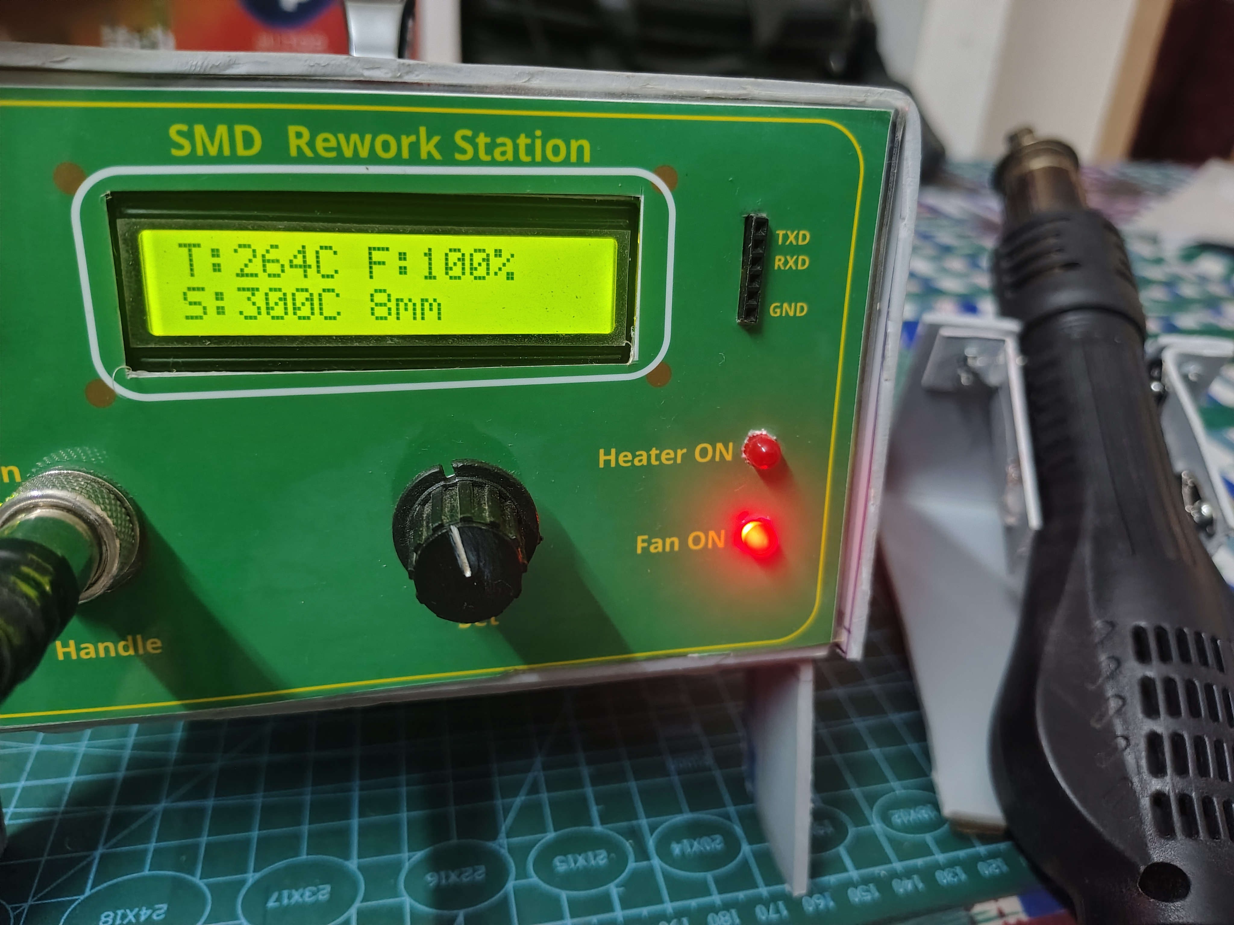
🧩 Hardware Architecture

The system is built using two dedicated PCBs:
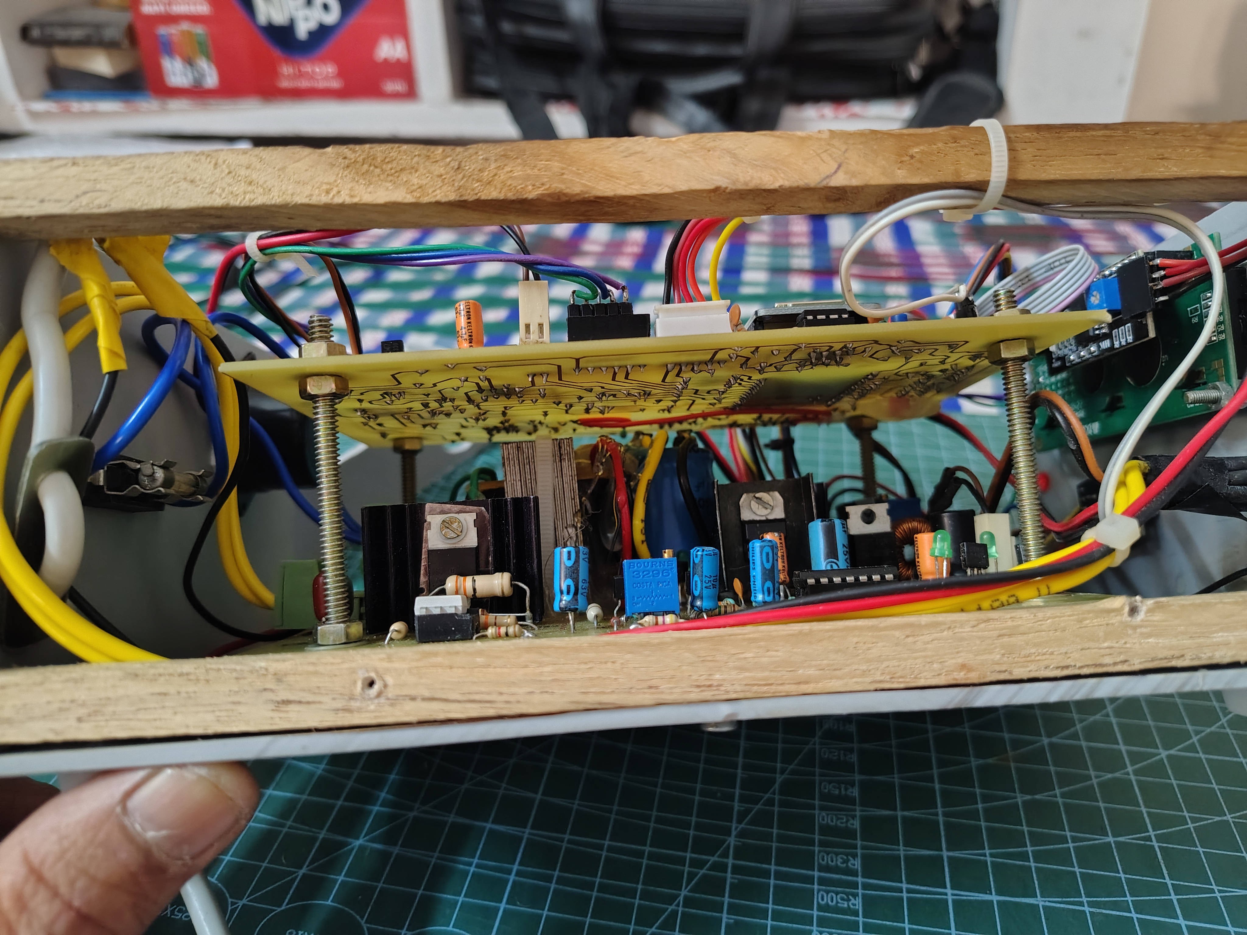
🔌 Power Board

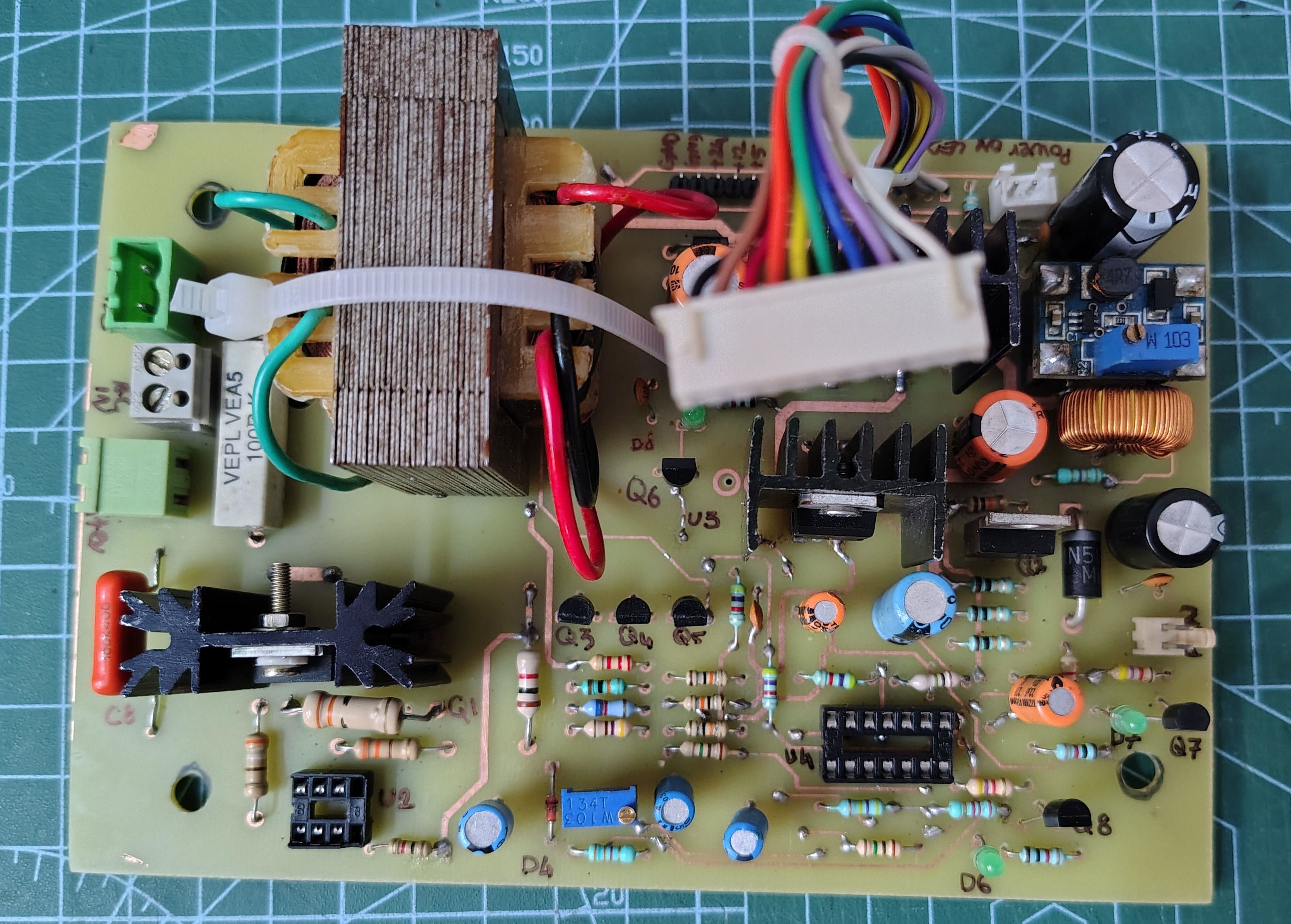
  • Controls 230V heater (~550W) using TRIAC (BT139)
  • Opto-isolated driver using MOC3041
  • Fan control via MOSFET(PWM)
  • Generates regulated 12V and 24V rails
  • Designed for high-current handling and isolation

👉 The MOC3041 is socket-mounted, enabling:

  •        Easy replacement
  •        Safe experimentation during initial bring-up
  •         Faster troubleshooting
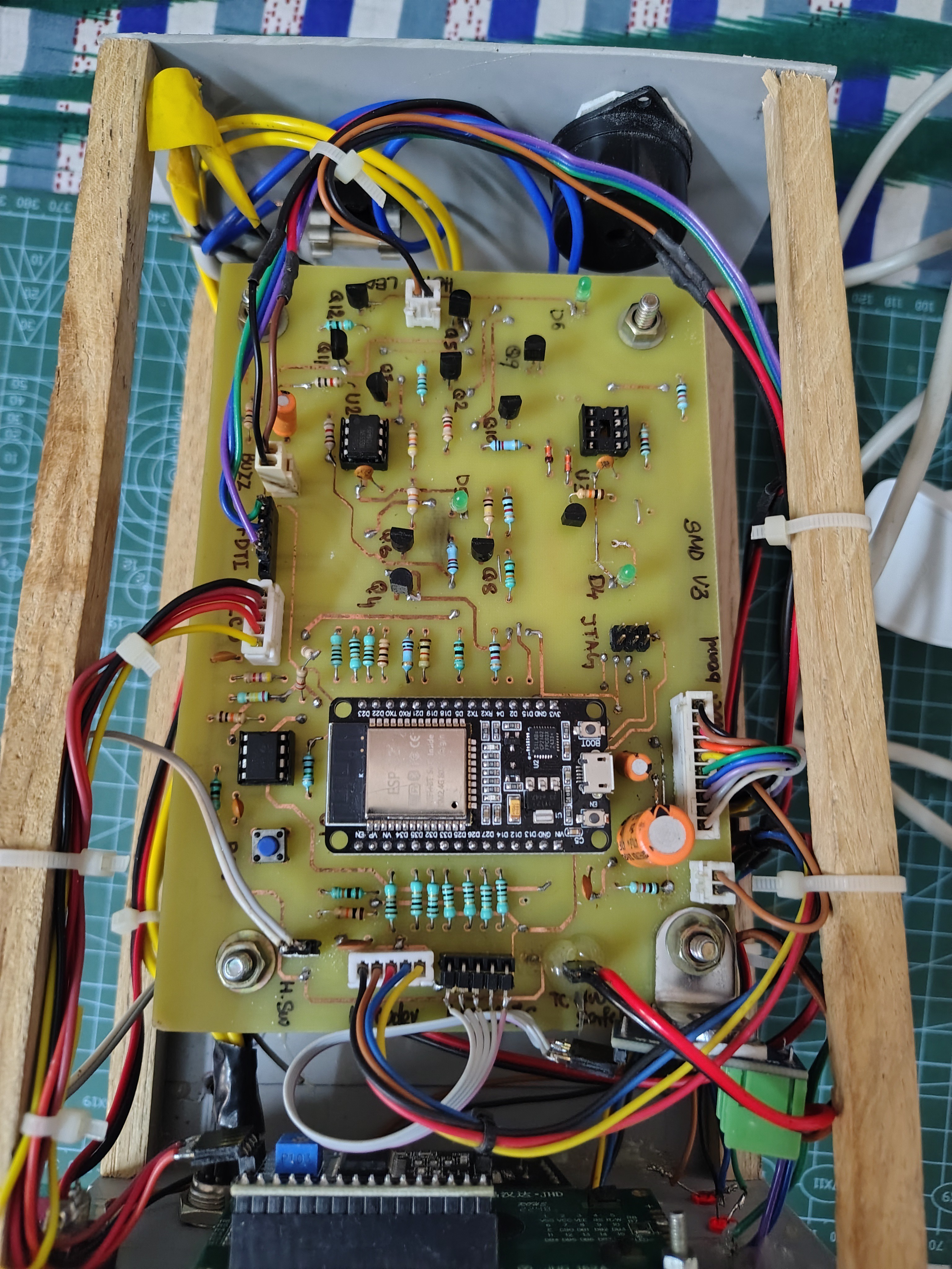
🧠 Processor Board

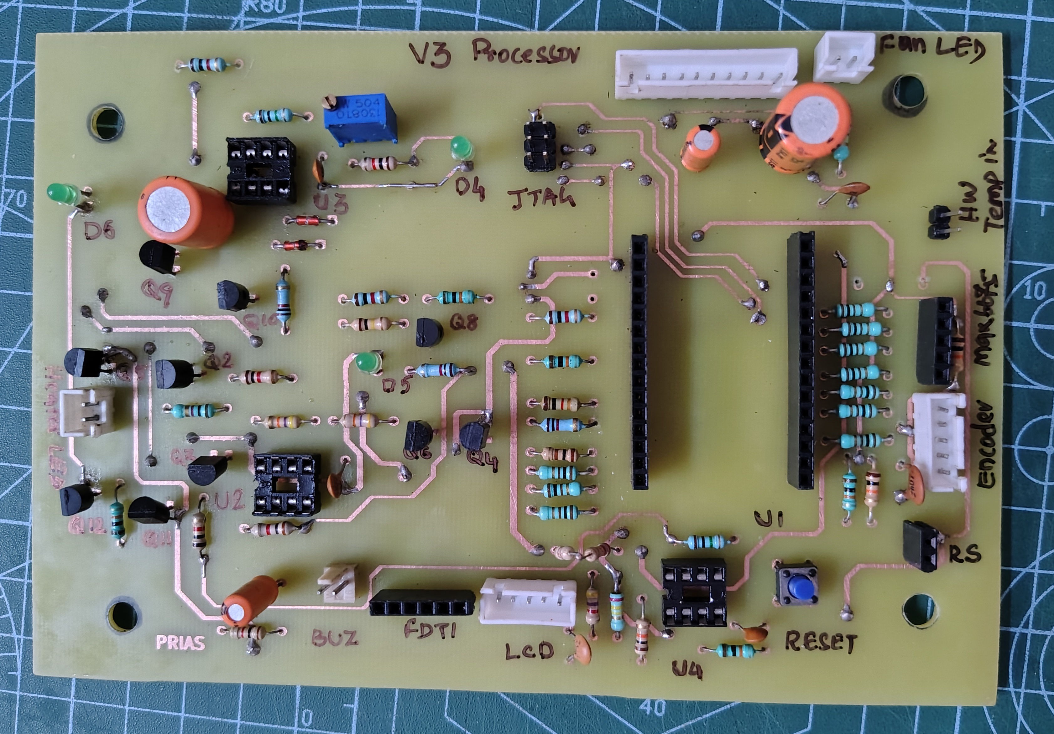
  • ESP32 DevKit controller
  • MAX6675 K type thermocouple interface
  • Rotary encoder input
  • 16×2 I2C LCD display
  • Control signal for heater and fan

⚙️ Firmware Architecture

  • The firmware is developed entirely in MicroPython.
  • A cooperative scheduler architecture is implemented to avoid blocking delays and ensure deterministic timing.

 This allows simultaneous handling of:

  •       PID temperature control loop
  •       User interface and menu system
  •       LCD  updates
  •       Safety monitoring

🌡️ Control & Operation

  • PID-based temperature regulation
  • Real-time thermocouple feedback (MAX6675)
  • 24V fan with PWM control
  • Rotary encoder-driven user interface

📋 Menu System & Nozzle Management

The system includes a structured menu interface for:

  • Selecting nozzle profiles
  • Setting temperature
  • Adjusting fan speed
  • Starting/stopping operation


🔧 Nozzle Features

  • Add new nozzle profiles
  • Store individual temperature presets
  • No restriction on number of nozzles


🎯 Calibration

  • Individual nozzle calibration supported
  • Re-calibration possible when:
  •      Operating conditions change
  •      Fan settings vary
  •     Thermal characteristics shift

🛡️ Safety Features

  • Fan–heater interlock (heater disabled without airflow)
  • Watchdog protection
  • Power supply monitoring
  • Thermal limits enforced in firmware

🔌 Power Design & Debugging

During development, system instability was observed due to:

  • Insufficient bulk capacitance
  • Voltage regulator dropout (7812 under load)

Fix implemented:

  • Increasing reservoir capacitance from 1000 µF to 5000 µF
  • Improving power stability under dynamic load

 This significantly improved system reliability.

🔧 Troubleshooting Features

To aid debugging and maintenance:

  • Dedicated status LEDs for:
  •       Power rails
  •       System states
  •       Fault conditions
  • Modular PCB design allows:
  •       Independent subsystem testing
  •       Easier fault isolation

🏭 Complete In-House Development

The project was developed in-house:

  • Circuit design
  • Schematic capture
  • PCB layout and etching
  • Assembly and wiring
  • Firmware development
  • System testing
  • Enclosure fabrication

🛠️ Build Difficulty

Intermediate → Advanced


Requires experience with:

  • 230V AC systems
  • Power electronics
  • PCB fabrication
  • Embedded programming (MicroPython)

🧪 Development Highlights

  • Stable scheduler-based firmware (V5.2)
  • Reliable fan operation across full PWM range
  • Accurate temperature regulation
  • Robust safety implementation

 Full project details, including firmware, schematics, and documentation, PCB files are available on GitHub:

👉 https://github.com/snivasms/SMD-Rework-Station

  • Temperature Overshoot in Hot Air Control – Implementing Software Tapering

    Srinivasan M S2 hours ago 0 comments

    During initial testing of the temperature control system, a noticeable overshoot was observed when the heater approached the set temperature.

    The system uses PID-based control with thermocouple feedback. While the steady-state regulation was reasonably stable, the heating phase exhibited a tendency to exceed the target temperature before settling back.

    This behavior was more pronounced at higher temperature settings and during rapid heating cycles.

    Initial investigation suggested that the issue was not with sensor accuracy, but with the control response near the setpoint. The heater, being a relatively high-power element, continued to deliver residual heat even after the control output was reduced.

    To address this, a simple software-based tapering approach was introduced.

    Instead of allowing full control output until the setpoint is reached, the system gradually reduces heater drive as the temperature approaches the target. This effectively softens the control action near the setpoint and reduces thermal inertia effects.

    After implementing this change:

    • Temperature overshoot was significantly reduced

    • Settling time improved

    • Control behavior became more predictable

    This approach proved to be effective without requiring major changes to the PID parameters.

    It highlights the importance of considering system dynamics and thermal inertia in addition to pure control loop tuning.

    Would be interested to know how others handle overshoot in similar thermal control systems.

  • Power Supply Debugging – Resolving 7812 Dropout and System Instability

    Srinivasan M Sa day ago 0 comments

    During the initial testing phase, the system exhibited unstable behavior, particularly when the fan and control electronics were operating simultaneously.

    The 12V rail, derived using a linear regulator (7812), showed noticeable voltage drop under load. This resulted in erratic system operation, including unreliable fan startup and inconsistent control behavior.

    At first, the issue was suspected to be related to firmware timing or PWM interaction. However, further measurements revealed that the root cause was insufficient bulk capacitance on the rectified DC supply.

    The original design used a 1000 µF reservoir capacitor, which proved inadequate for handling transient load demands from the fan and control circuitry. Under load, the input voltage to the 7812 regulator dropped below its required dropout margin, causing the regulated 12V rail to sag to approximately 10.6V.

    To resolve this, the reservoir capacitance was increased from 1000 µF to 5000 µF. This significantly improved voltage stability by reducing ripple and maintaining sufficient headroom for the regulator during peak load conditions.

    After this modification:

    • The fan started reliably across the full PWM range

    • The control system became stable

    • Temperature regulation operated consistently

    This debugging process highlighted the importance of proper power supply design, especially in systems combining high-power loads with sensitive control electronics.

    Ensuring adequate bulk capacitance and understanding regulator limitations are critical for stable operation.

View all 2 project logs

Enjoy this project?

Share

Discussions

Similar Projects

Does this project spark your interest?

Become a member to follow this project and never miss any updates