 Tony Goacher
There's full instruction on how to make your own here.
I've used the Sparkfun sound detector module in several other projects and I've been impressed with it's performance when used with the appropriate demo software here by Michael Bartlett. It's one of the best DIY sound to light applications I've seen.
The first unknown was will the detector board run from 3.3V. The board specifies a supply voltage between 3.5 and 5.5V, with 5V being 'ideal'. The board uses an LMV324 op amp, and the datasheet for this states a supply voltage between 2.7V-5V.
I tested this by hooking the board up to a bench power supply. It did work, but I found it significantly less sensitive at this voltage. However, the gain of the circuit can be changed by adjusting the value of R3 and I found a value of 200k seemed to work well. This is an 0805 style device so it's pretty easy to swap for someone with basic soldering skills.
I needed to get the sound detector board connected to the tildagon, the Hexpansion ports were the obvious choice for this. The software requires an analog input, but not all hexpansion ports have this.
I chose port 4 (J4) as this will minimise the width when wearing the badge.
I couldn't be bothered designing a dedicated PCB, so I ordered the excellent Protoboard Hexpansion by Jake Walker from Etsy
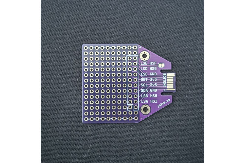
It arrived in a few days and only costs £3.37 (~$4.50) so quite a bargain. Thanks Jake!
The design uses a potentiometer as a software sensitivity control. I wanted this to be integral to the hexpansion so I created a 3D printable mount that uses the hexpansion fasteners and holds everything together.
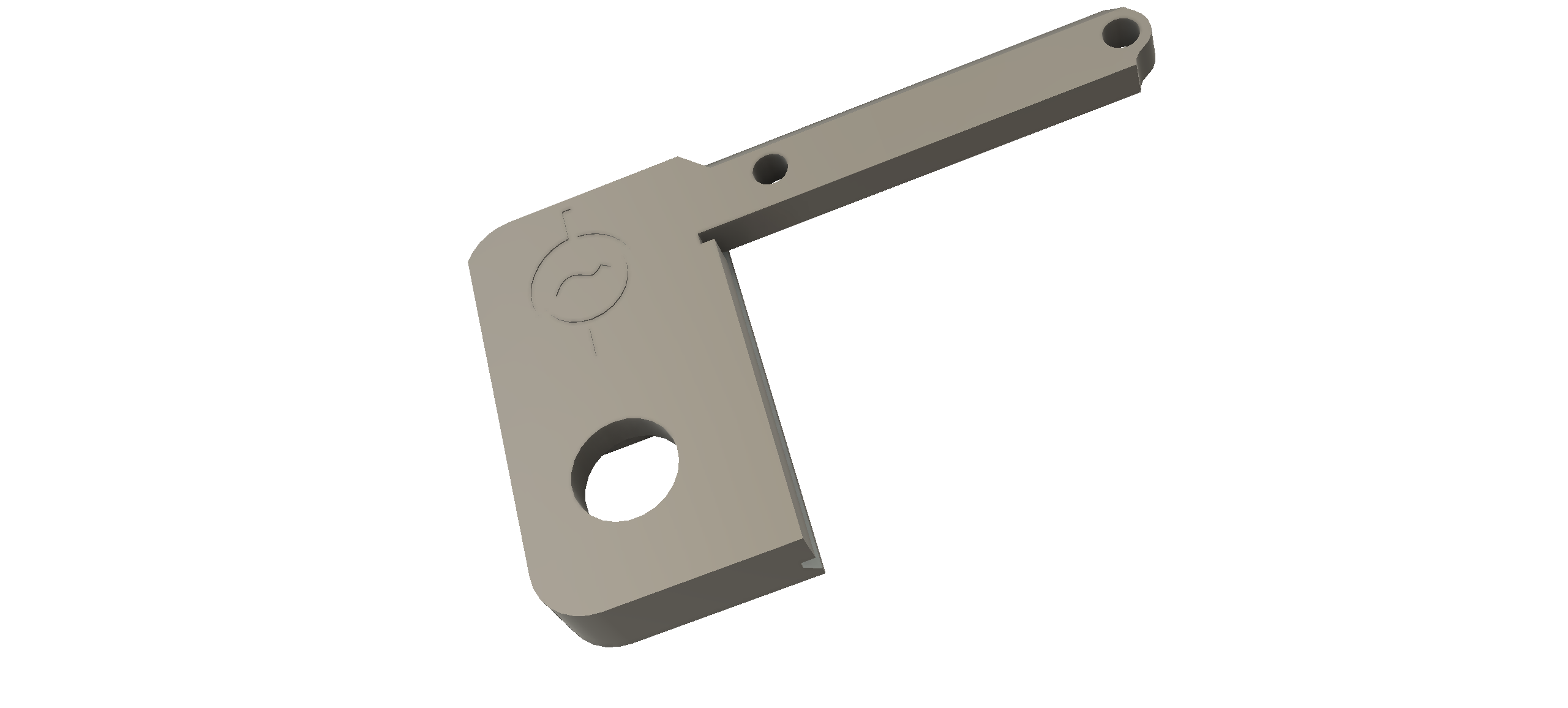
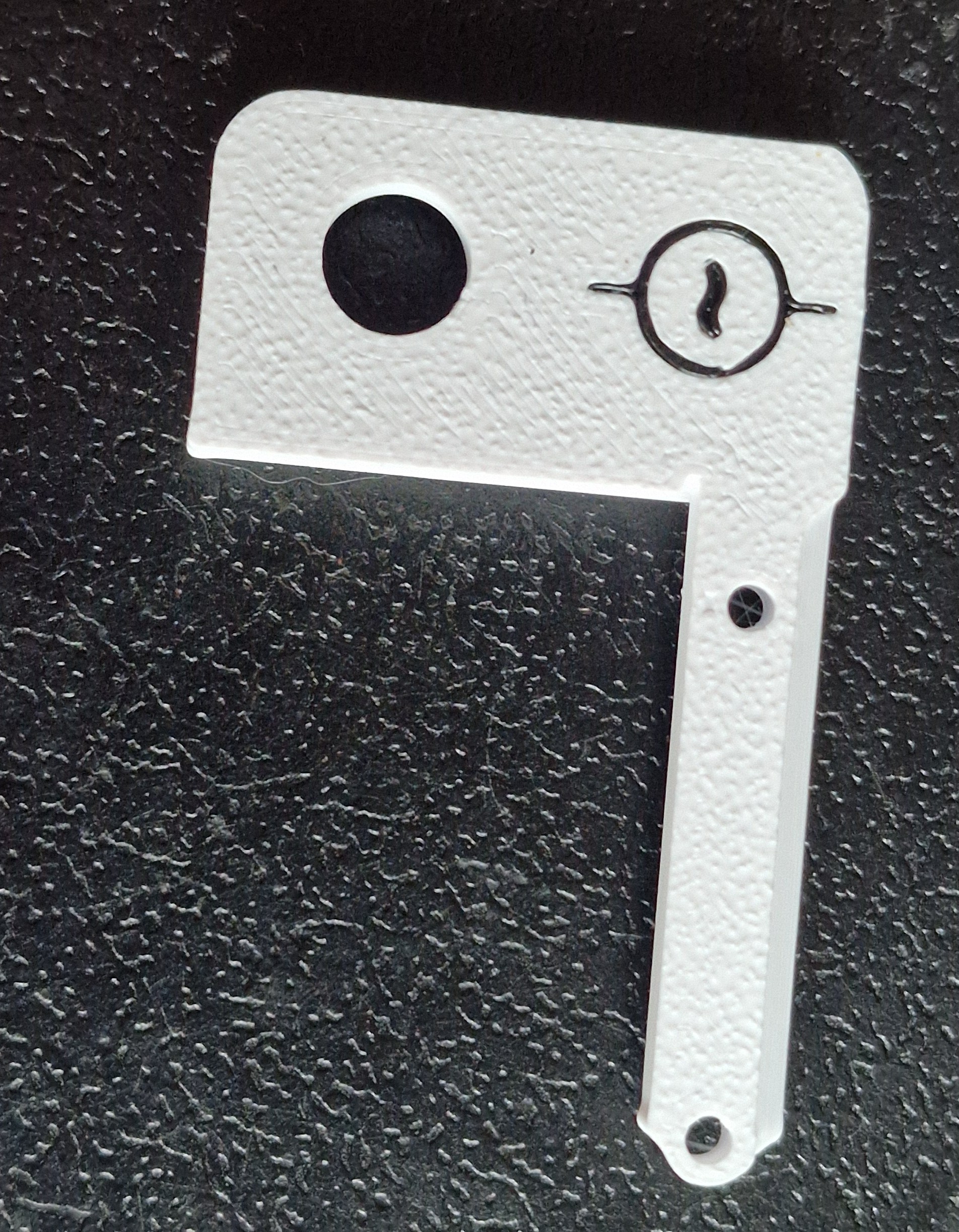
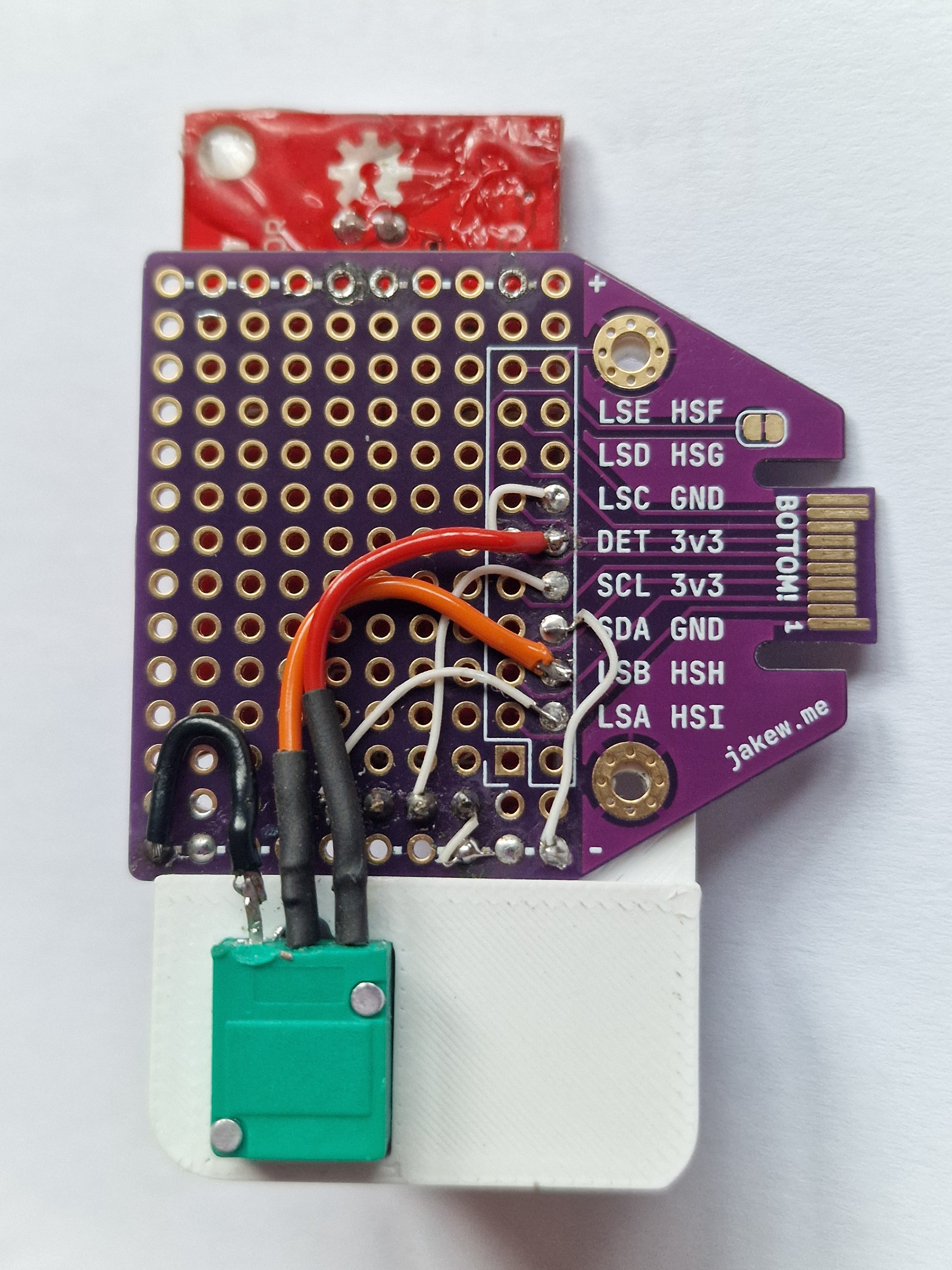
I used hookup wire to connect the sound detector board the the appropriate hexpansion pins. One noteworthy connection is that the DET pin must be connected to GND, otherwise the tildagon does'nt see the hexpansion as present, and won't supply power.
The following connections are required:
| DET | GND |
| 3V3 | Sparkfun VCC |
| 3V3 | Potentiometer A |
| GND | Potentiometer B |
| GND | Sparkfun GND |
| HSH | Potentiometer wiper |
| HSI | Sparkfun Envelope |
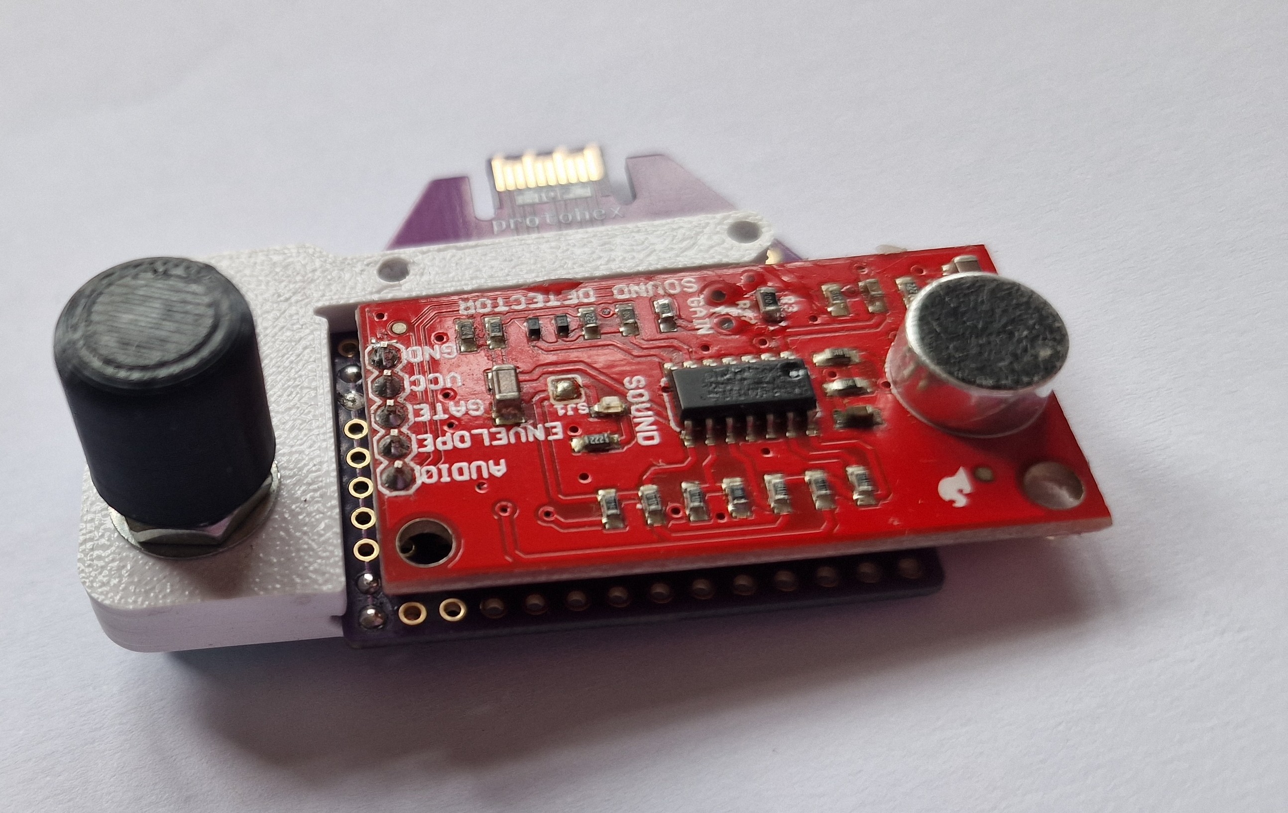
The original demo software was written in C and needs a 20ms loop time to enable it to detect edges from the analogue output of the sound detector. The tildagon OS provides an App class which includes an update() function. When an app is running, this is called 'roughly' every 0.05s.
I found this to be not tight enough for the software to reliably work, so I broke all the rules by not returning from the update() function and using an internal 20ms delay. This worked fine except it killed the OS polling of the buttons making the app impossible to exit.
I bodged around this by returning control to the OS every 1000ms. This probably will kill any other apps running on the board, but sound to light uberalles. It also makes the button responses sluggish and I need at least one button to change the lighting mode. I got around this by returning to the OS more frequently for a period after the mode button has been detected. If no buttons are detected within a certain time, the app goes back to hogging the CPU.
I'm a C/C++ guy so I found the coversion to Python none trivial but I got there in the end and learned a lot.
Discussions
Become a Hackaday.io Member
Create an account to leave a comment. Already have an account? Log In.