 Jacob Busshart
-
1Step 1 — Parts and Laser Safety
Parts can be found in the Components section or on the GitHub
Total cost lands around 750 €, dominated by the filters, surplus spectrometer and laser safety glasses.
Notes on the two "wildcard" parts:
- Spectrometer: the BTC100-2S is the cost compromise of this build. Its 100 µm slit is the main resolution bottleneck. Any spectrometer covering roughly 500–650 nm will work — a better one yields sharper peaks, though often at significant cost.
- Objective: must be infinity-corrected — the design places the dichroic and longpass filter in collimated space and uses the achromat as the tube lens. A finite (160 mm) objective will not work without redesign! Also keep in mind that anything >20x often features a working distance too short for measuring inside containers or a cuvette (though at higher NA = more signal). 20x is the best compromise, from my experience at least.
This build uses a 532 nm laser at >30 mW — a Class 3B laser. Direct exposure and even specular reflections can cause permanent eye damage before you can blink.
- Certified laser safety glasses rated for 532 nm are mandatory. Buy from a reputable supplier, not AliExpress. I use these from Protect Laserschutz (~130 €).
- Keep the laser disconnected from power during the entire assembly. It is only powered once fully enclosed in the cube.
- Never look into the beam path or the objective, even with protection on.
- Remove watches and rings while aligning — stray reflections mostly come as a surprise.
- Know your local regulations for Class 3B laser operation.
-
2Step 2 — 3D Printing Notes
All parts print without supports, and each is printed only once (except where noted in the parts table on GitHub). I printed on a Bambu P1S with a 0.4 mm hardened steel nozzle, sliced in BambuStudio.
Material: ideally dark, non-reflective, and stiff. I used black PETG-CF (matte, my favorite); PLA-CF is a sensible alternative.
Settings:
- Layer height 0.12 mm — at least for anything with threads or fine features
- 4 walls, 50 % gyroid infill
- Seam position Nearest (or Random) for better thread fit
- "Precision" parameters set to 0.001 mm (may just be placebo)
Orientation: print faces flat / perpendicular to the build plate — especially threads, which must be printed vertically for clean engagement. "Auto-Orient" should always do the trick.
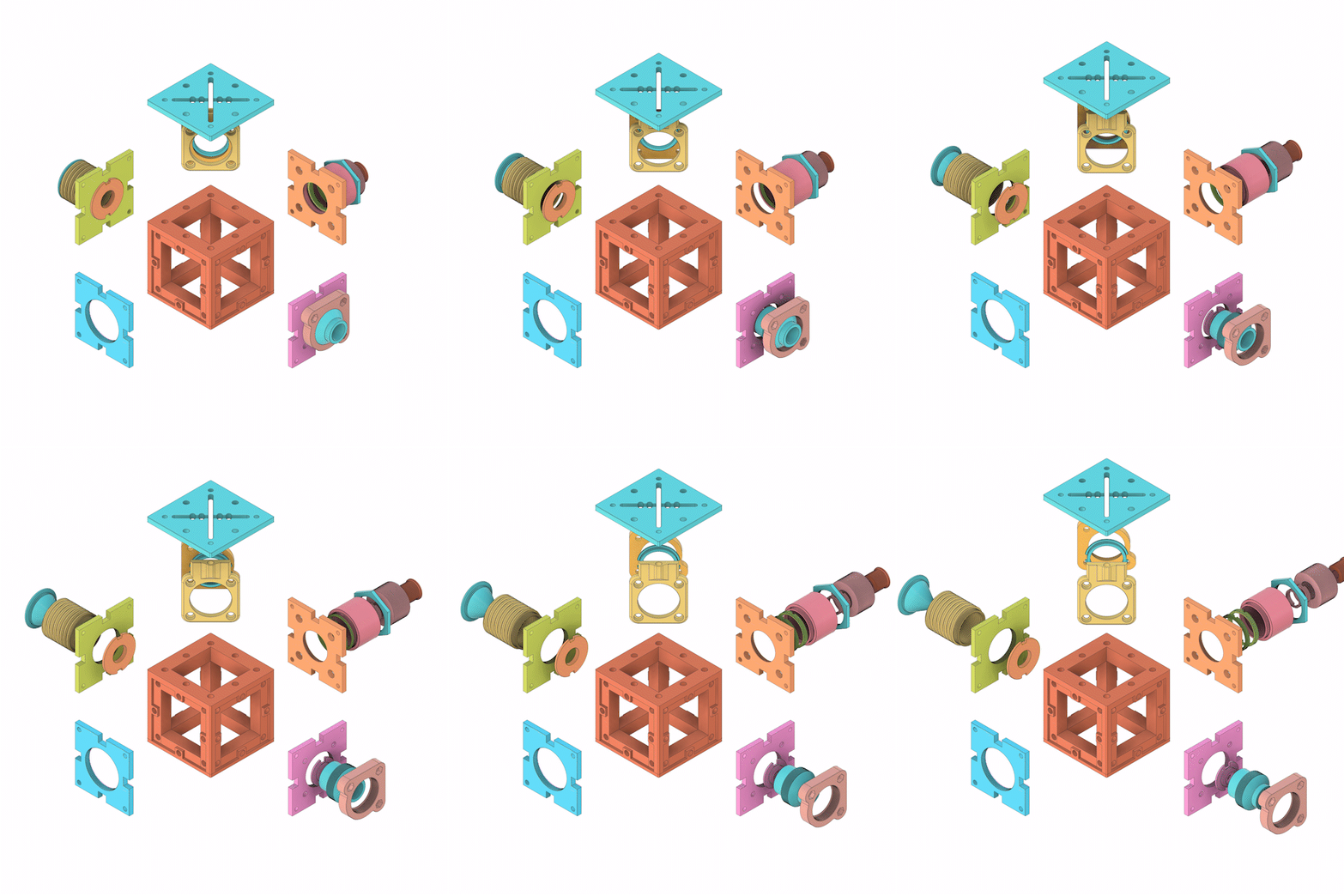
![]() Overview Graphic; be aware that parts might have been slightly modified!
Overview Graphic; be aware that parts might have been slightly modified!Order & tips:
- Print Base-Cube, Base-Cube-Top and the four Cube-Inserts (Sample, Dump, Laser, FilterFocus) first, then the remaining grouped parts.
- The Base-Cube is the most demanding part due to overhangs — everything else is easy.
- For the Cube-Inserts and Cube-Lid, let the build plate cool fully before removal, or you risk permanently warping the part.
- Also print the two spanner tools (Spanner_SM1RR, Spanner_SM05RR) — they make tightening the retaining rings much easier later.
-
3Step 3 — Base Cube
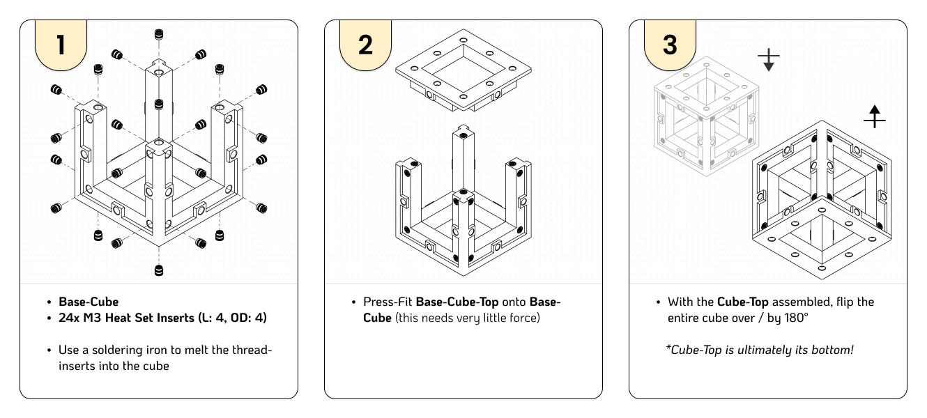
Printed: Base-Cube, Base-Cube-Top
Sourced: 24× M3 heat-set inserts (4 mm length, Ø4 mm), 24× M3×8 screws
![]()
- Melt the heat-set inserts into the bosses of the Base-Cube using a soldering iron. Keep the iron perpendicular and let the plastic — not force — do the work.
- Fasten Base-Cube-Top with M3×8 screws.
You don't have to populate every insert at first. I initially left out the bottom row and one full side — the side that later takes the Beam Dump — because that opening doubles as access to the adjustment screws of the 45° mirror inside. The Cube-Insert clearances are relatively tight (tighter still if the cube's overhangs sagged a little), and during testing I ran most inserts on just 2 screws (top-left + bottom-right).
The following sub-assemblies (Steps 4–7) don't need to be built in order.
-
4Step 4 — Laser Sub-Assembly
Printed: Cube-Insert_Laser, Laser-Kinematic, Laser-Insert, BP-RR (only if using the bandpass filter)
Sourced: 532 nm laser (Ø12 mm), bandpass filter #65640 (recommended), 4× magnets (Ø6×2 mm), 3× M3×8 screws + nuts (fine-pitch 0.35 preferred, standard works)
![]()
- Press the magnets into the openings on Cube-Insert_Laser. Since the mating part (Laser-Kinematic) rides on 3 screws, 3 magnets are technically enough — but the fourth also blocks stray light.
- Press the M3 nuts into Laser-Kinematic. For best results, thread a screw in and tap the screw head with a hammer to seat the nuts flush and fully home. (If you want them permanent, a soldering iron can lightly melt them in — not necessary with current clearances.)
- Friction press-fit the laser module into Laser-Insert. Make sure the laser's front face sits perpendicular and flush.
- Press the bandpass filter into the other side of Laser-Insert. Orientation matters — the two faces carry different coatings: the purple side should face you (so you see purple when assembled). Keep the laser disconnected. Never look into the laser, even with protection on.
- The filter should already sit tight; lightly screw on BP-RR until it secures the rim.
- Screw the assembled Laser-Insert into the printed thread of Laser-Kinematic.
- Seat Laser-Kinematic on Cube-Insert_Laser — the magnets preload it against the 3 kinematic adjustment screws, which give the laser its tip/tilt.
- Press the whole insert into a side of the Base-Cube and fasten with 4 screws.
Powering the laser: the module is specced for 3.7 V, but I run it at 2.7–3.0 V from a bench supply via its two bare leads (or via a voltage regulator from a powerbank now). Higher voltage doesn't buy a cleaner beam — just more heat (I'm not using the heatsink yet, as my magnets are too weak to carry the added weight) and more noise. The lower range has been the better operating point in my measurements.
-
5Step 5 — Sample Port / Objective
Printed: Cube-Insert_Sample (M32 thread; an M25 variant is in the repo — email me for others)
Sourced: 20x infinity-corrected microscope objective
- Confirm your objective's thread matches the printed part.
- Position the objective perpendicular to the printed thread and carefully thread it into Cube-Insert_Sample. The first engagement takes noticeably more force — that's the printed thread forming itself.
- Once the objective sits flush against the insert's surface, press the assembly into the side to the left of the laser insert (as in the exploded graphic) and fasten with 4 screws.
Note on working distance: the objective's working distance decides what you can measure through container walls. Mine is 2.4 mm — enough to measure ethanol through a plastic bottle wall, and by shifting focus you pick whether you see the ethanol or the polypropylene of the bottle itself.
-
6Step 6 — Dichroic Mirror (45°)
Printed: Mirror-Kinematic, Mirror-Backplate, Mirror-RR, Cube-Lid
Sourced: Thorlabs DMLP550, 3× M3 screws + nuts, magnets (Ø6×2 mm)
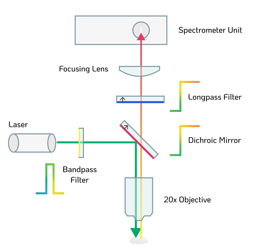
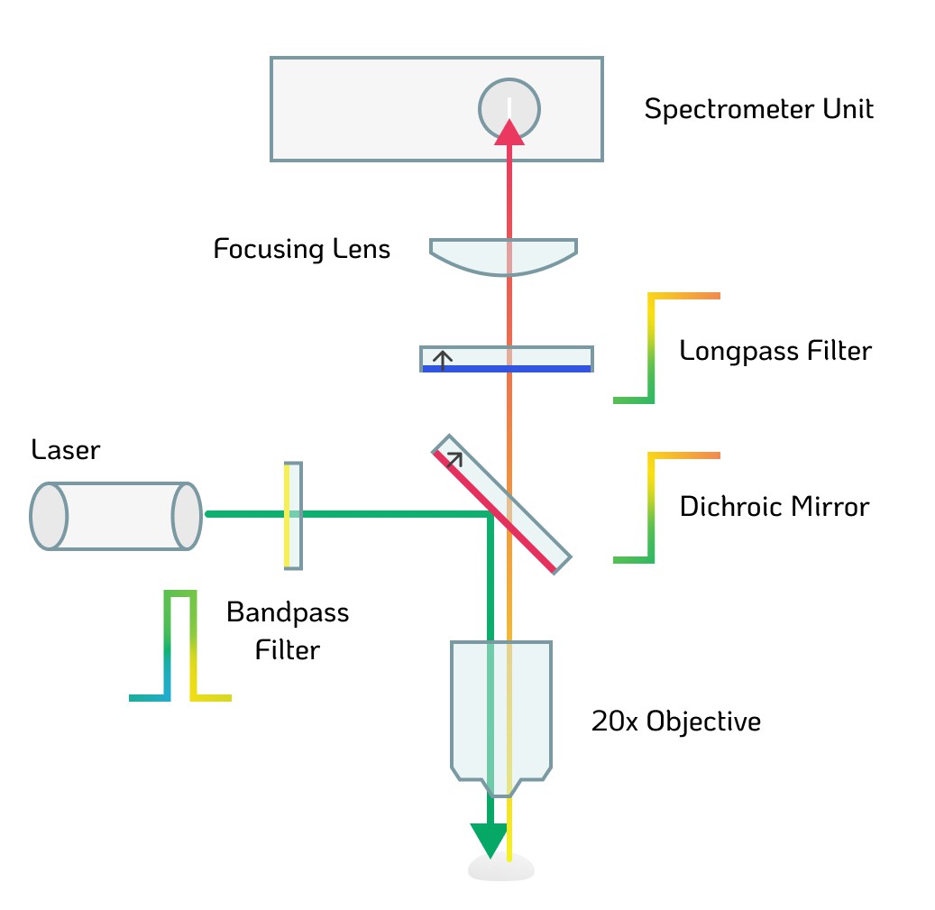
Be mindful of the orientation of both the FELH0550 and the DMLP550 as they have to be installed in the correct orientation. Make sure the direction on the rim of both optics corresponds with the arrows in the graphic below:
![]()
- Seat the DMLP550 in Mirror-Kinematic's 45° pocket and secure it with Mirror-RR. Handle the dichroic by its edges only — fingerprints on the coating directly cost you signal.
- Press the M3 nuts and magnets into Mirror-Backplate / Mirror-Kinematic as in the laser assembly: the magnets preload the mirror platform against the 3 adjustment screws, giving the dichroic its tip/tilt.
- Lower the mirror assembly into the Base-Cube and close the top with Cube-Lid.
- The adjustment screws remain reachable through the (still open) beam-dump side of the cube for alignment later.
-
7Step 7 — Beam Dump
Printed: Cube-Insert_Dump, Dump-Body, Dump-Cone, Dump-Aperture
Sourced: nothing
![]()
- Screw the printed parts together: Dump-Body is the main part and threads into Cube-Insert_Dump.
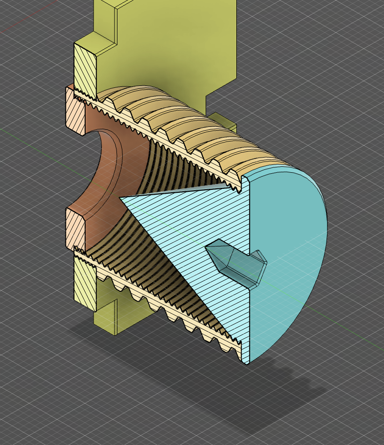
- Screw on Dump-Cone to create a light-sealed cavity.
- Dump-Aperture screws on from the opposite side. It isn't strictly necessary, but can improve light suppression.
The dump sits opposite the laser: the laser light that transmits straight through the dichroic (plus Rayleigh-scattered 532 nm returning from the sample) ends up trapped here instead of bouncing around the cube. The whole dump is deliberately modular so different cone angles and aperture sizes can be swapped and tested. Leave this insert unscrewed until alignment (Step 9) is done — its opening is your access port to the mirror adjustment screws.
-
8Step 8 — Filter & Focus Tube + Spectrometer Coupling
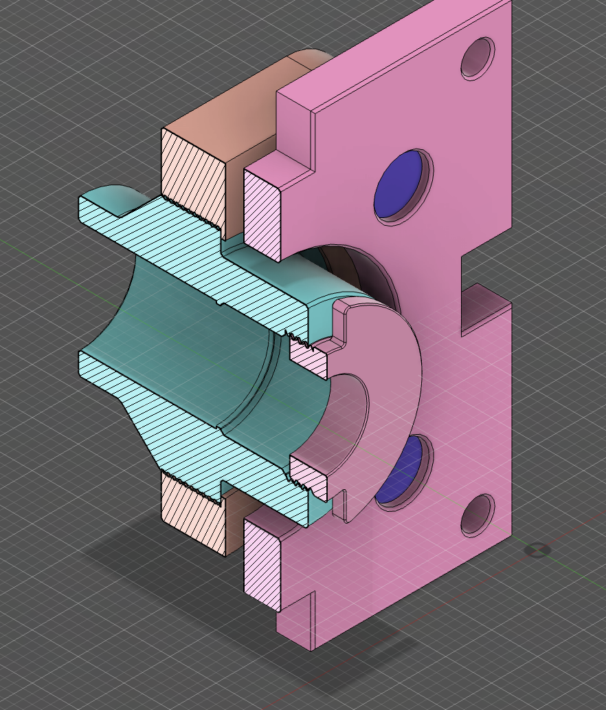
Printed: Cube-Insert_FilterFocus, SM1-Tube, SM05-Tube, SM1-Lockring, SMA905-SM05, 2× SM1-RR, 2× SM05-RR (+ the two spanners)
Sourced: FELH0550 longpass filter, AC127-019-A achromat, B&W Tek BTC100-2S
![]()
Screenshot only depicts 3d-printed parts!
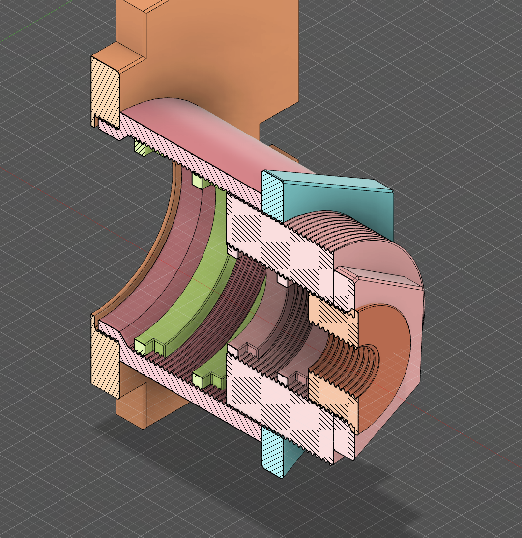
This is the detection arm: collimated Raman light exits the dichroic, gets a second stage of Rayleigh rejection from the longpass filter, and is focused by the achromat onto the spectrometer's 100 µm slit.
Be mindful of the orientation of both the FELH0550 and the DMLP550 as they have to be installed in the correct orientation. Make sure the direction on the rim of both optics corresponds with the arrows in the graphic below:
![]()
- Thread one SM1-RR into the SM1-Tube as the lower seat — it defines the axial position of the filter.
- Drop in the FELH0550 and clamp it flat with the second SM1-RR from above. The printed rings are only 2–2.5 mm thick and somewhat flexible: thread them in with pure rotation, no downward force, keeping them as perpendicular as possible so the filter sits truly square. Use the printed spanner — it engages the two openings in each ring and keeps them from going in crooked.
- Mount the achromat in the SM05-Tube between the two SM05-RRs, same technique. Orientation matters: the more strongly curved surface faces the collimated beam (toward the cube), not the focused end — check this when you take the lens out of its shipping mount.
- Thread the SM05-Tube into the SM1-Tube. The relative thread position of the two tubes is your focus adjustment onto the slit.
- Couple to the spectrometer with the SMA905-SM05 adapter — the output of the lens tube screws directly onto the SMA905 input of the BTC100-2S. Clean and rigid, no fiber run between optics and detector. (Alternatively, use the optional SMA905 fiber, ~200 µm core, if you want the spectrometer positioned remotely, though this might require additional adjustment options for efficient coupling.)
- Mount the tube assembly on Cube-Insert_FilterFocus and fasten the insert into the cube face opposite the sample port. Once focus is finalized during alignment you can optionally clamp everything with the SM1-Lockring.
Spectrometer hookup: 5 V / 2 A+ barrel-jack supply for power, RS232-to-USB cable to your computer. I reuploaded the original SpectrumStudio Software here. (Alternatively you can write your own software to communicate with the spectrometer via the serial connection.)
-
9Step 9 — Alignment & First Light
Calibrating the spectrometer unit is an important prerequisite that needs to be performed using either a calibration lamp or any CFL (with a known spectrum) or mercury vapor lamp. For this you acquire a spectrum of exclusively said lamp in a dark room, navigate spectrum studio and write down pixel index and then match with the corresponding reference spectrum from your source. When you have more than 4 points sampled — ideally as many as you can get — you put them into the table in SpectrumStudio, which then automatically calculates the correct calibration coefficients.
⚠ Glasses on. Room cleared of reflective clutter. Lowest usable laser voltage (~2.7 V).
- With the beam-dump insert still off, power the laser and check that the beam hits the dichroic centrally and exits through the objective.
- Use the laser's kinematic screws (magnet-preloaded tip/tilt) to center the beam on the objective's back aperture; use the mirror's kinematic screws — reached through the dump opening — to make the beam exit the objective straight and centered.
- Place a strong Raman scatterer with a spectrum you know at the focus. Good first samples: polypropylene (any PP container), isopropyl alcohol, or — if you have one — a diamond, whose single sharp line at 1332 cm⁻¹ can be a nice start.
- Take continuous acquisitions (around 1000 ms acquisition) while slowly adjusting the SM05/SM1 tube focus and the sample distance until the Raman peaks maximize. Expect this to be iterative between laser tilt, mirror tilt, and focus.
- Lock the SM1-Lockring, install the beam dump, and close up the cube.
For liquids in containers, remember the working-distance rule from Step 5: thin-walled vials/cuvettes work best; thick glass mostly returns the silica spectrum of the glass itself.
-
10Step 10 — Acquiring & Processing Spectra
The raw output of the spectrometer is intensity vs. wavelength (nm), typically with a sloping fluorescence background and the occasional cosmic-ray spike. The repo includes CubeRaman-SpectrumPro, a vibe-coded Python GUI that turns the raw CSV into a legible Raman spectrum:
- Raman-shift conversion — wavelength → wavenumber relative to the 532 nm excitation, with cropping to the usable 600–3000 cm⁻¹ window
- Cosmic spike removal — modified Z-score detection on the derivative, with interpolation across spike events
- Baseline correction — choice of ALS, arPLS, or SNIP algorithms for fluorescence/background removal
- Smoothing & normalization — Savitzky–Golay filtering, 0–1 normalization
- Peak detection & fitting — pseudo-Voigt profiles with FWHM readout
- Library matching — compare against reference spectra with peak-position scoring and cosine similarity, with overlay plots and CSV export (only if you have a library file, as I unfortunately can't provide that)
Peak fitting is honestly more relevant for high-resolution, calibrated instruments — on this build the 100 µm slit dominates peak width — but detection and matching work well: polypropylene, paracetamol, isopropanol, and ethanol all identify cleanly (see the sample spectra on the project page).
CubeRaman: 3D-Printed Raman Spectroscopy
An easily reproducible, compacted iteration of my first Raman build. Using a surplus spectrometer, cheap laser and high-quality filters.
Discussions
Become a Hackaday.io Member
Create an account to leave a comment. Already have an account? Log In.
Hi! I'm very interested in this project, and I have a Ocean Optics USB2000+ spectrometer (which I think has similar specs to yours). Do you have a guess for how long the aluminum cube will take to design? I'm a big of an optics noob (I've messed with lasers some, but not this power level), and I think it would make me slightly more comfortable to have a more robust core to the project. Also, I wonder if it's possible to put it inside another enclosure to further protect against stray laser light while it's assembled and in use?
Are you sure? yes | no
Hi there! Thanks for reaching out. The USB2000+ should be well suited, if not better, I believe. I hope I can pick up the more capable CNC next weekend and then get somewhat accustomed to it. The aluminium version will be an almost entirely different architecture - so not a cube. Realistically it will be up in 3+ weeks, though you can reach me via e-mail (Jacob@Busshart.de), then I could send you the files before documenting everything properly to showcase on here. And sure, the more enclosure the better broadly speaking :p
Are you sure? yes | no