 blinknbuild
What We Built in 24 Hours (And What Nearly Killed Us)
This entire project was designed, wired, coded, and tested in a single 24-hour hackathon session.
The first 2 hours were component triage — figuring out what we had and what was compatible. The live camera stream was a last-minute addition when someone grabbed an ESP-CAM from the parts bin at hour 6.
The biggest technical fight was the MQ9 sensor supply voltages. We had both sensors reading garbage for the first 3 hours. The CO sensor was on 5V — outputting saturated readings regardless of actual gas. Fix: CO sensor needs 3.3V, LPG sensor needs 5V. Once sorted, readings made sense.
The ESP-CAM integration was surprisingly smooth. Instead of a serial link, we made it join the ESP32's own WiFi AP and stream over HTTP. The dashboard embeds the stream URL as an image source. Simple and it works.
IR wall-following turned out far more reliable than expected. The bot ran 8+ minutes without collision in the test corridor.
Code: https://github.com/Nikhil-A-E/Gas-Leak-Detection-Bot
Video:
Key Wiring Decisions and Why We Made Them
A few wiring choices in this build aren't obvious from the schematic alone.
Why two batteries:
One 2S LiPo powers the motors through the L298N. A second powers all logic through the breadboard PSU. This isolates motor noise from sensor supply rails. Running everything from one battery caused ADC spikes every time a motor started — motor current draw dragged supply voltage down, showing up as false gas readings. Separate supplies fixed this completely.
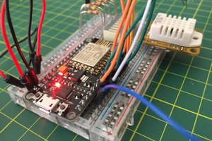
Why GPIO15 as a power output:
GPIO15 is set HIGH in software at boot and stays there — it becomes a 3.3V source pin for sensors. It's a strapping pin that must be HIGH at boot anyway, so it's a natural choice. Sensors draw very little current, well within what the ESP32 can supply.
Why input-only pins for sensors:
GPIO34, 35, 36 (VP) have no internal pull resistors and cannot be outputs. This makes them ideal for analog sensor inputs — no accidental output state, no pull affecting the ADC reading.
What We're Adding Next
Power: Two 2S LiPo packs are clunky. A single 3S (11.1V) would feed the L298N directly and run the PSU from the same source — simpler wiring, more capacity.
Gas sensors: MQ-135 covers CO2, NH3, benzene, smoke, and alcohol in one package. Replacing both MQ9s simplifies wiring and broadens coverage. Tradeoff: less specificity about which gas triggered.
Mapping: The current dashboard map is dead reckoning from the MPU6050 yaw angle. It drifts badly. Real SLAM would make it actually useful for locating a leak source.
Logging: Nothing is persisted right now. SD card logging would store timestamped gas readings + position estimates even when WiFi is out of range — useful in industrial environments.
 Tony Kambourakis
 Owen
Owen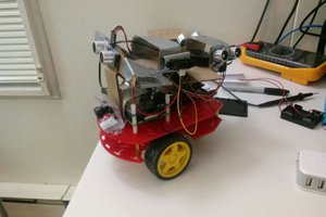
 Sinclair Gurny