 Muth
Muth
There’s definitely a pattern in these projects. Do I need repetitive tasks to relax ? Do I need scaling-up a simple concept until it becomes unreasonable ? We go again with flipdots, I had a pile of used 7-dots segments, with half-bridge integrated circuits to drive them.

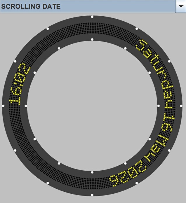
Can we imagine a non-standard flipdots matrix? What about a ring instead of a rectangle? With around 300 segments, the angle between them drops below 2°, which is good enough to make the circle feel continuous and visually acceptable.

And it’s now almost natural to see it as a clock.

Designing the electronic board. Let’s settle on 24 segments per board. This doesn’t fully use the FP2800a capabilities, but it keeps the board size and cost reasonable, and improves the refresh rate. That still means 12 boards for a 288 × 7 dot “matrix”. The way for the half bridge to work in matrix requires 2 diodes. There is so many information on internet about flipdot driving.

The data bus of each FP2800a needs to be driven for every dot flip, we select a row, a column and the current direction. If we use shift registers and a decent refresh rate, it can result in quite a high data rate. Flipdots behave essentially like small solenoids, and will induce electrical noise. I went for daisy-chained PIC microcontrollers to drive the two FP2800a per board.

KiCad sessions were a bit challenging, especially working with angles. It is 4 layers boards, with board-to-board power and signals connectors. And then comes the matrix routing. Coil-driving tracks avoid as much as possible the signal lines.


After very few days of waiting the JLCPCB boards to arrive, the long soldering sessions were delightfully relaxing.


PIC Software: This part turned out to be more subtle than expected. A tricky 24-byte circular buffer had to be implemented in the PIC. The natural daisy-chain for SPI it only 1 byte buffered. At first the SPI interrupt code generated by MCC was too slow, so I had to optimize it to reach 100 kHz SPI clock. I imagined a kind of protocol for display data latching and configuration. Only 7 bits of each of the 24 bytes are used as it is 7 dots segments. The remaining bits are used for board configuration and a data checking byte. For example, the option bits allows to configure the flipping time (how long the coil receive current, from 0.1 to 1.5 mS), or if we force the driving of dots that are in theory already in the correct position. These parameters can be tweaked according to the refresh rate needed, and give space for experimentation. The FP2800a consumes a few mA each. With 24 of them, this is not negligible. So the PIC powers them via a GPIO to save energy when idle. A 5 ms timer is reset on every received SPI byte. If there is a pause of 5 ms or more, the data is latched and the dots are driven, this is a sort of soft framing mechanism.
Powering and consumption: One of the goals was to keep the clock completely wireless. As a clock, updates only happen once per minute, the average power consumption stays surprisingly low, making battery operation realistic. And the thing is big, there is enough space for several cells. I selected 5× 18650 Li-ion cells to get close the 24V needed to flip the dots. We need a 5S battery management board, a step-down module for 5V, and a step-up module 24V.

There is a substantial difference between regulator modules, notably the idle current. I measured up to 12mA background current on cheap modules. However, modules from Pololu consume less than 1mA when idle.

Mechanical structure: With this size and weight, 3D printed plastic blocks will lack rigidity. The back plane skeleton is a single aluminum plate, and was cut with a water jet thanks to helpful colleagues.


So far, I have the following features: – WiFi hotspot for setup from a computer or phone – Time synchro once per day via NTP – Night mode: dots updated only every 10 minutes for quieter...
 The code is here :

 alnwlsn
 Göran Nordahl
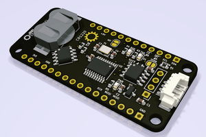
 John Whittington
This looks super cool! Where did you purchase your flipdots from? I'm a huge fan of anything that uses them