 cburns42
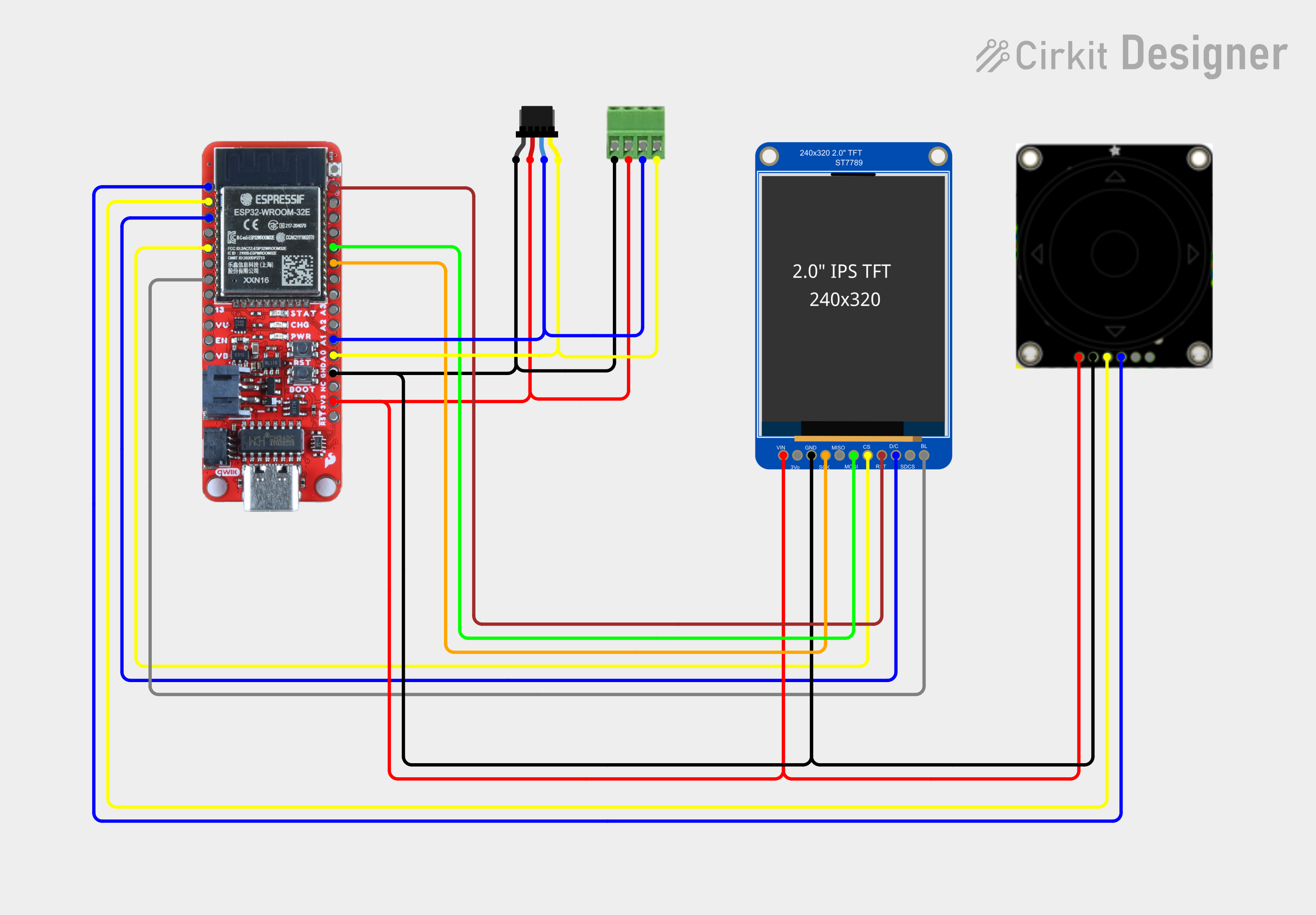
The goal of this project is to develop a tool that will be used to help diagnose issues with I2C buses. There are already a number of I2C scanners available, there is even one of the Arduino sample applications, so why invent another? This version is a stand-alone tool that does not require any external equipment. It uses a few simple components:
|  |
This tool is just the beginning or a larger project which will include several projects to implement accessory control for model trains.
This tool uses Arduino with the Adafruit graphics library, Adafruit ST7789 driver, and the Adafruit seesaw library for UI input controls. Google Material icons are used for various indicators.
A unique feature of this scanner is that it contains a small database of I2C devices. The data was collected from https://i2cdevices.org/ and https://github.com/adafruit/I2C_Addresses/. These were merged, flattened and indexed using a python script for use in an Arduino sketch. The implementation is lazy and very basic.
The implementation is a lazy implementation of an event loop UI. Lazy because it is a small UI that does not dictate a larger implementation using something like lvgl. The Arduino loop function is used to poll the rotary encoder and dispatch to various functions depending on the page in focus.
| The encoder uses up/down/right/left to move through UI elements which are highlighted, the center button selects elements. The rotary dial controls the display backlight level. |  |
The UI workflow consists of a small number of pages:
| On the start page, move the rotary encoder up/down buttons to move between controls. Selecting Scan will perform a scan with a 100 kHz clock. |  |
| Scan page has a grid containing a block for each address. Color codes indicate what was detected:
|  |
| To dive into details on the found device(s), move the rotary encoder left/right buttons to move between controls to the Grid icon, and press select. This enters a mode which moves the rotary encoder up/down/right/left to select a device. |  |
| If an invalid device is selected an error indicator turns on. |  |
| Moving to a valid discovered device and selecting will launch a details page. |  |
| Because device addresses are not unique, it is difficult to determine what device is present. The details section allows reviewing a list of devices that have that address. |  |
| Moving the rotary encoder left/right buttons and pressing select will move forward and backward through the descriptions. |  |
| Selecting the Speed Scan will cause scans to be performed multiple times (100 kHz, 400 kHz, 1 MHz). The Grid display will show the highest speed a device was found at. |  |
| The scanner page includes an indicator to scanning at multiple clock rates. |  |
| Selecting Continuous will cause scans to be performed every 250 milliseconds when on the Scan page. |  |
| The scanner page includes an indicator for continuous scanning. |  |
 mircemk
 Arky
Arky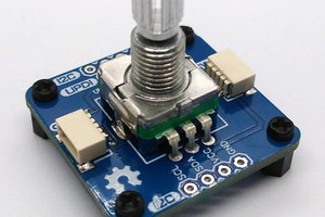
 Stefan Wagner