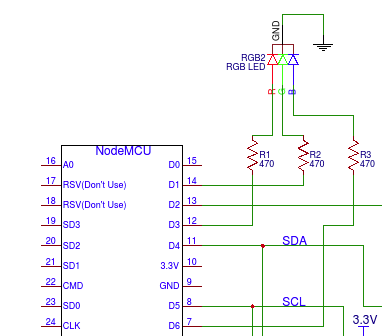
The RGB LED includes a pin for each colour and a ground. Each colour pin was connected to a port on the NodeMCU:
| RGB LED | NodeMCU | GPIO |
| R (Red) | D3 | GPIO0 |
| G (Green) | D1 | GPIO5 |
| B (Blue) | D6 | GPIO12 |
A 470Ω resisters was used for each colour.

The pins were assigned to status definitions in the code to make it easier to set their status:
// PIN definitions
#define OWNER_STATUS_IN 0 // D3 = GPIO0
#define OWNER_STATUS_OUT 5 // D1 = GPIO5
#define OWNER_MESSAGE  12 // D6 = GPIO12

pinMode(OWNER_STATUS_IN, OUTPUT);
pinMode(OWNER_STATUS_OUT, OUTPUT);
pinMode(OWNER_MESSAGE, OUTPUT);
To set the LED to Owner Status IN mode, switch ON the desired colour and switch OFF the other colours.
digitalWrite(OWNER_STATUS_IN, 0); // switch off
digitalWrite(OWNER_STATUS_OUT, 1);
digitalWrite(OWNER_MESSAGE, 0);
 Tony Kambourakis
Discussions
Become a Hackaday.io Member
Create an account to leave a comment. Already have an account? Log In.