Close
0%
0%

Limn: Pen Plotter with Toolchanger

Building a Pen Plotter with automatic toolchanger with components from an old RepRap style 3D Printer. Runs on Klipper.

Similar projects worth following
I've always wanted to build my own Pen Plotter that can change tools automatically. Limn can pick and use various tools with high degree of repeatability. Docking and undocking tools works well. The design is close to being stable now.

Inspired from E3D, the toolchanger uses a small stepper motor to actuate a rotating key that docks the tools. While the motor is quite low-torque, the geometry and the mechanism makes docking light weight tools possible.

The tools can also connect electrically to the printer using the docking pins, and with an RFID tag we can read and write tool specific parameters (such as offsets, tool properties, etc.) for automatic tool usage. Three pins are available, VCC, GND, and GPIO.

Levers and wheels on the toolhead make manual movement possible.

It is an open source and open hardware project in its early stages. Klipper configuration and hardware 3D models are available on Github. There will be a Printables project in near future.

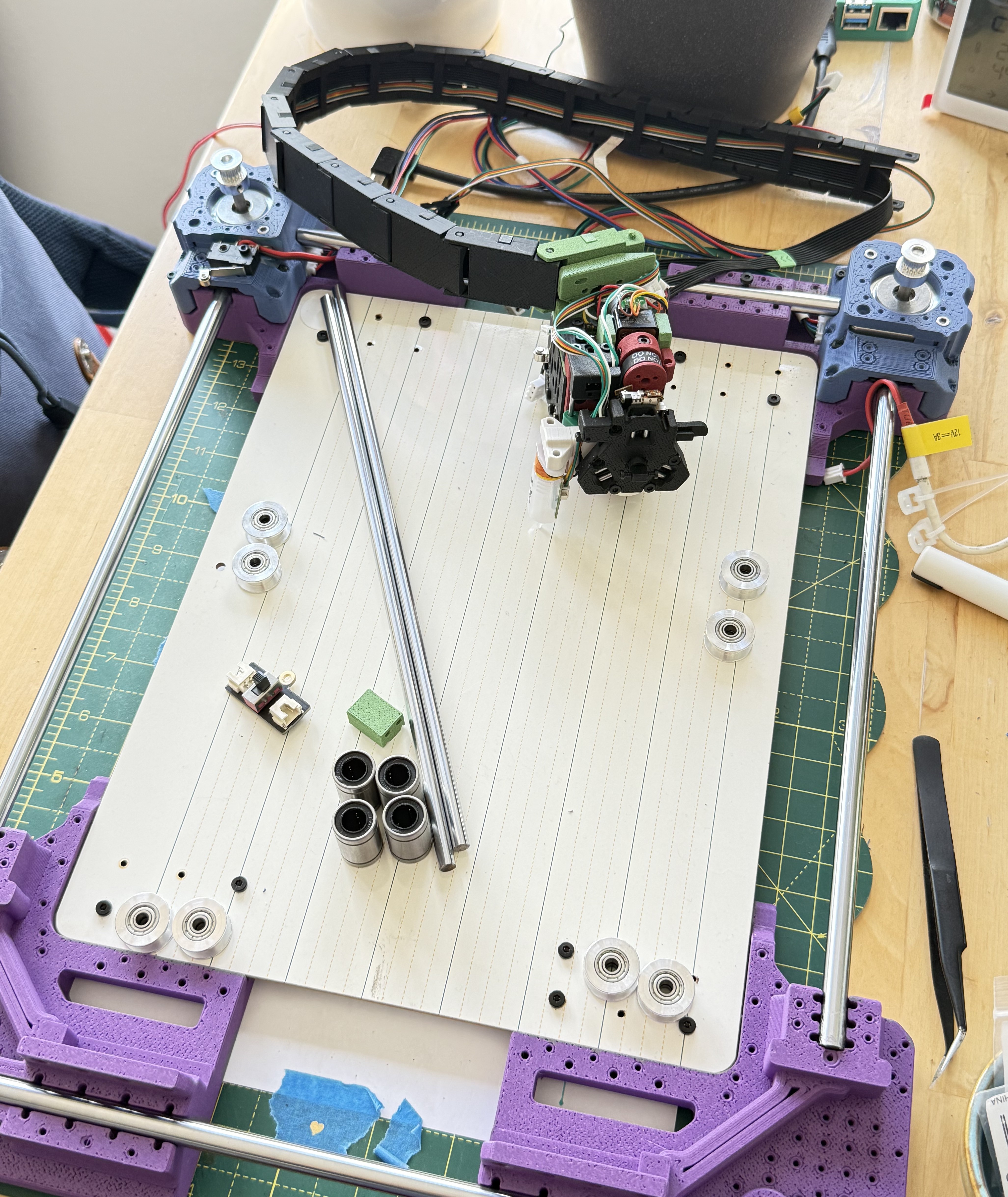
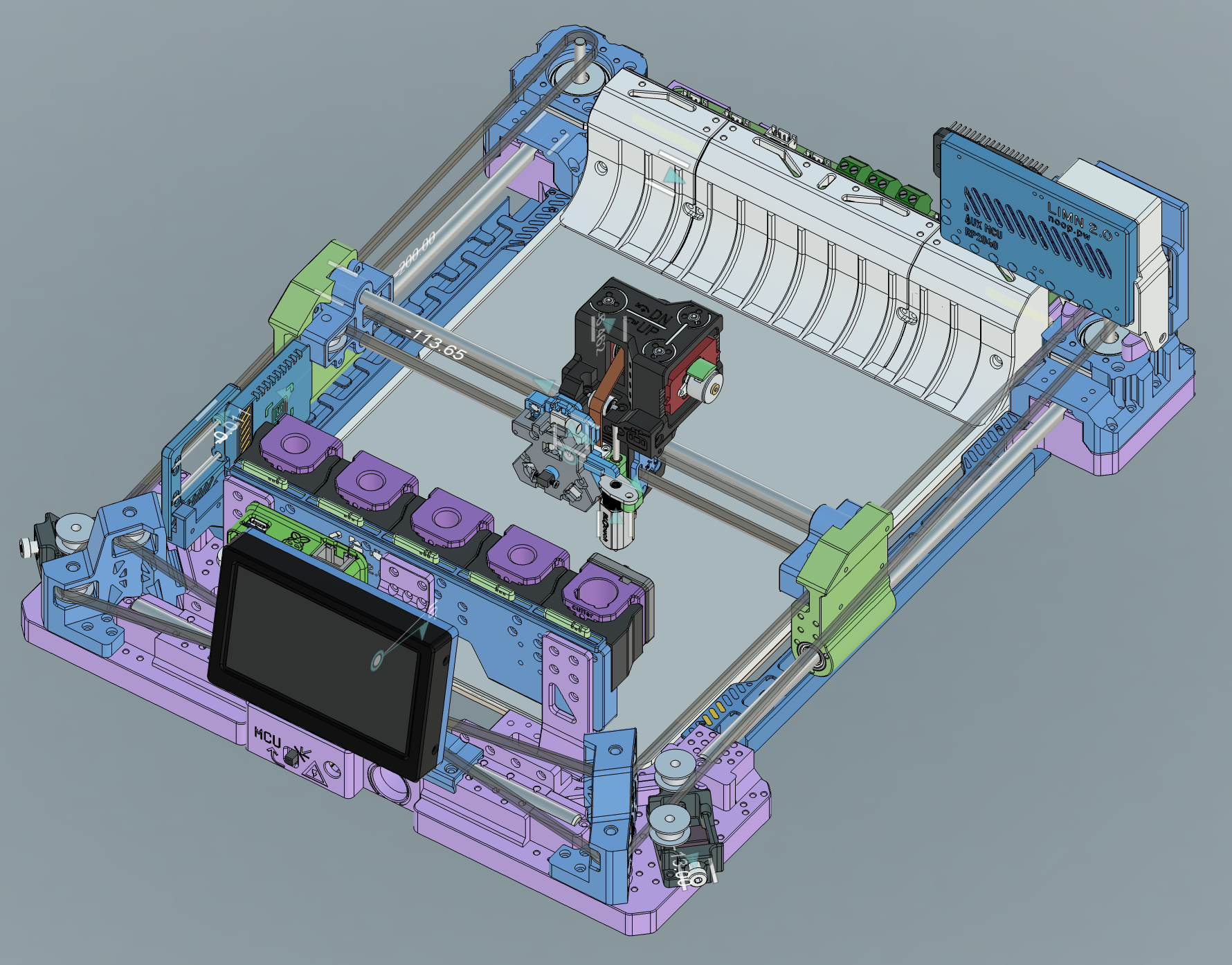
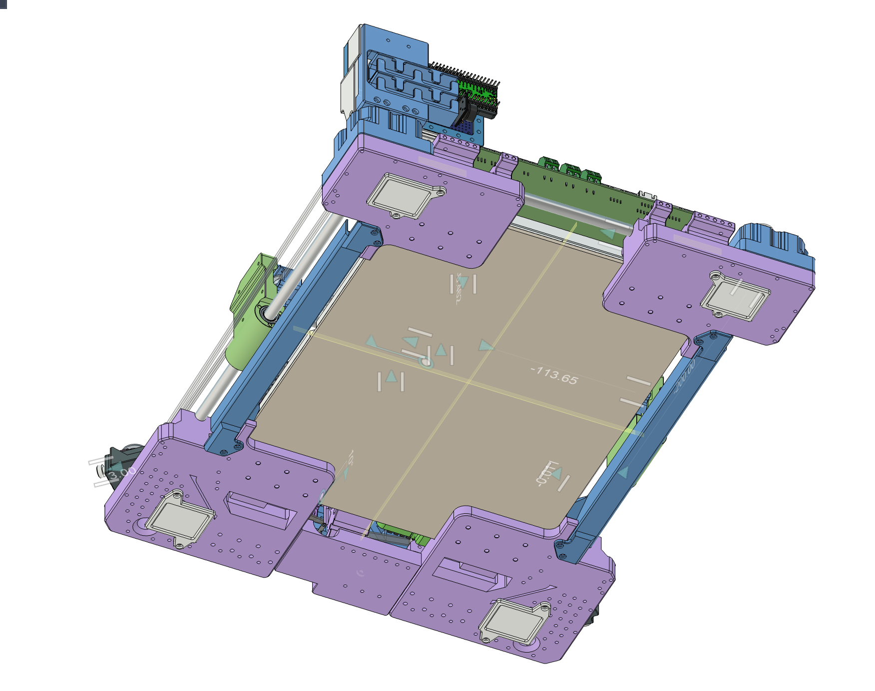
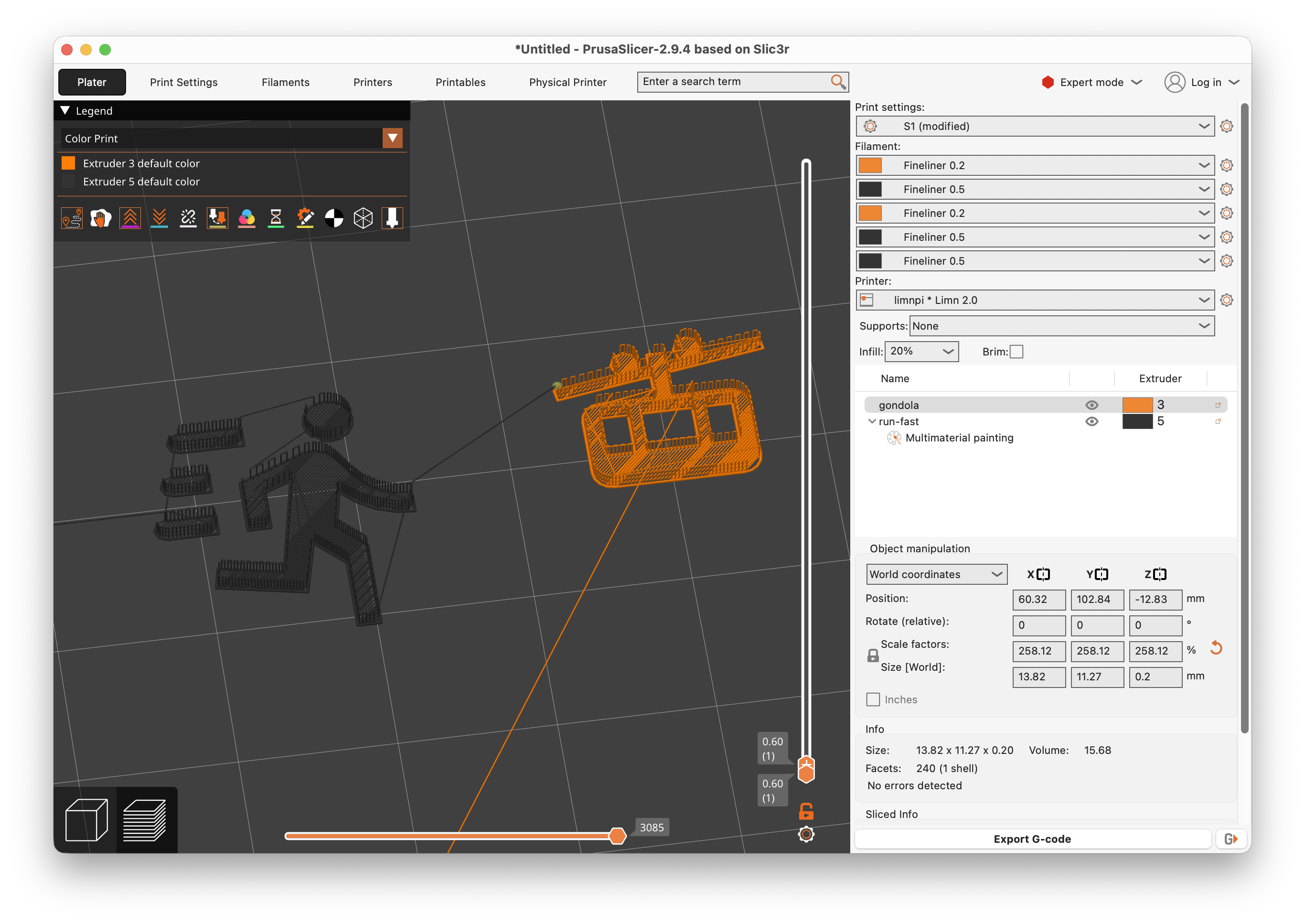
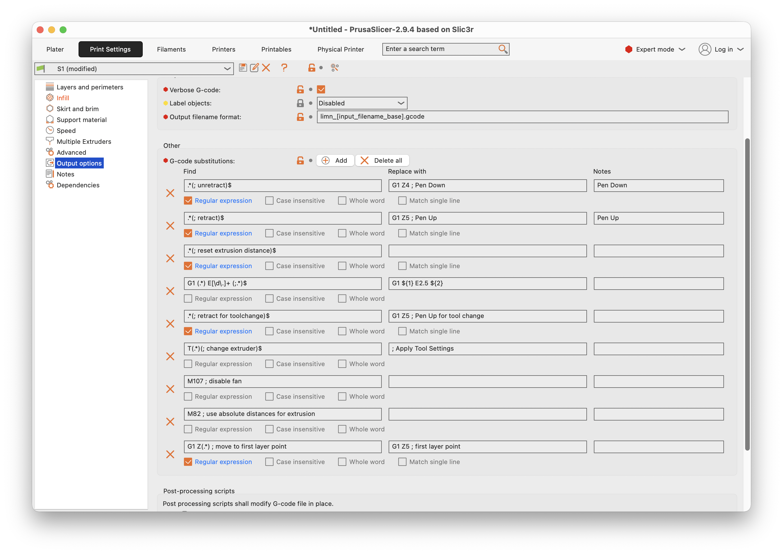
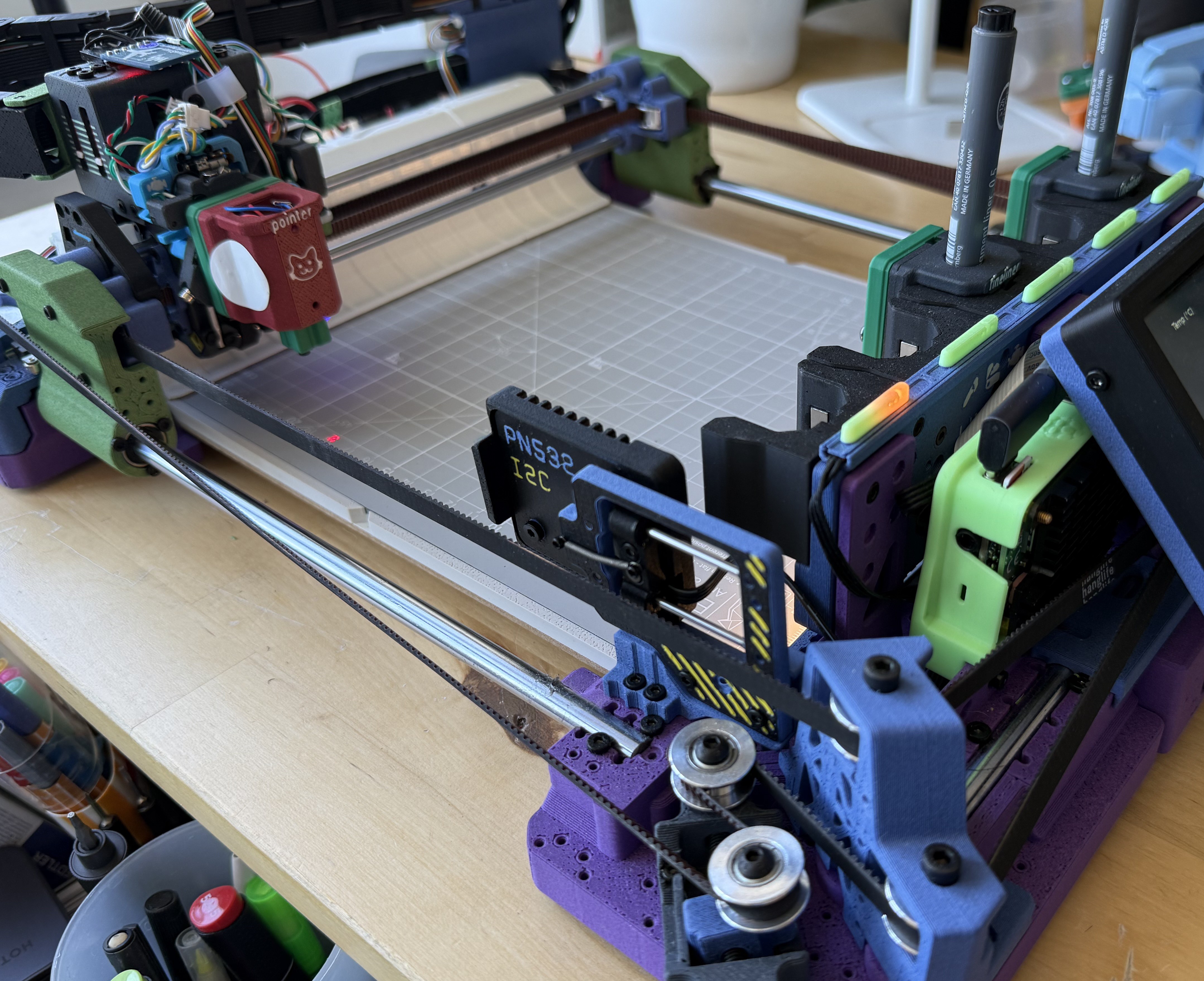
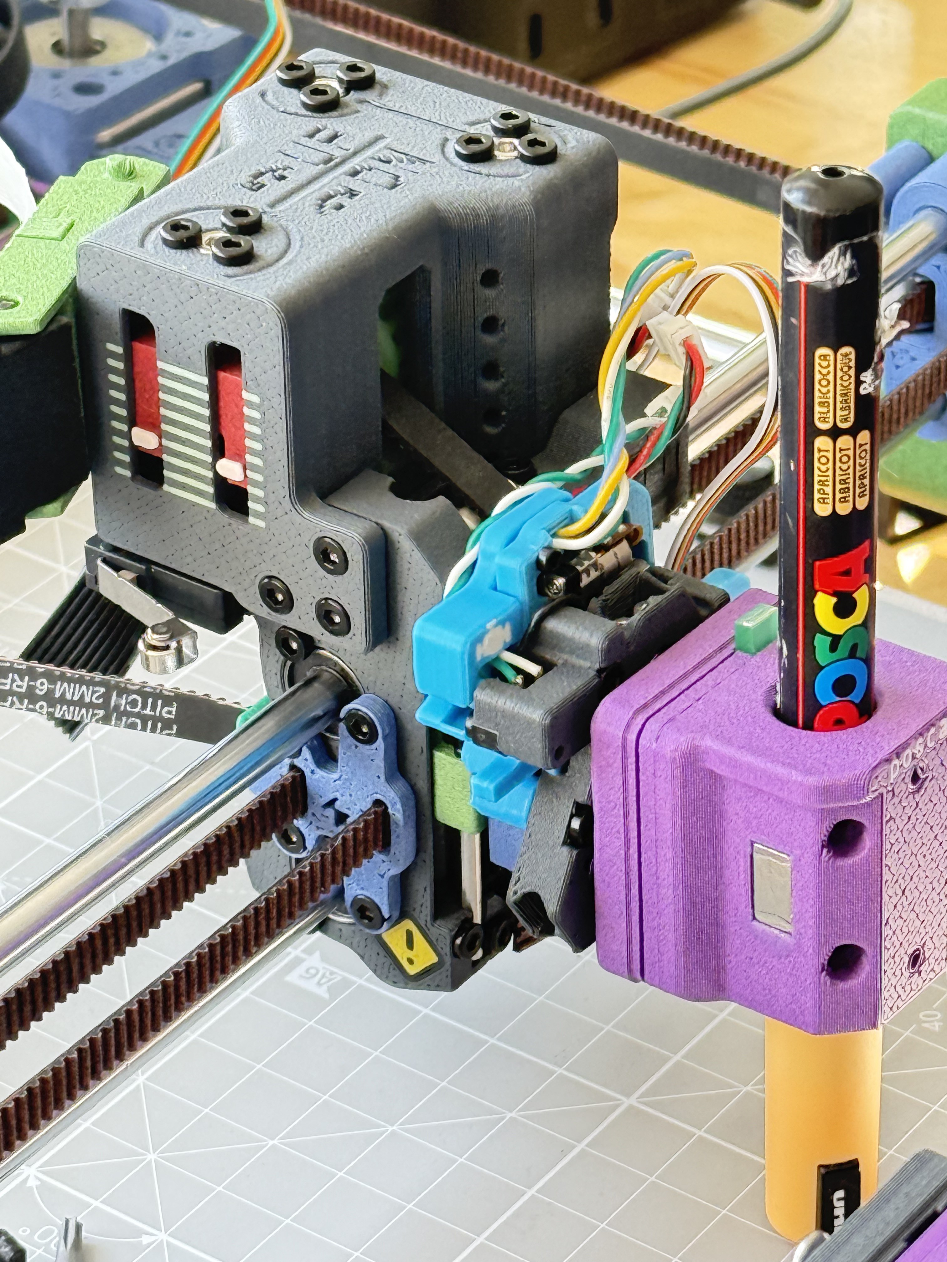
Limn is a Pen Plotter with an E3D style toolchanger. I built it using parts reclaimed from an old 3D printer, some new hardware parts, and 3D printed parts. It runs using Klipper and PrusaSlicer, similar to a regular printer.


Some key parts can be obtained from old 3D printers:

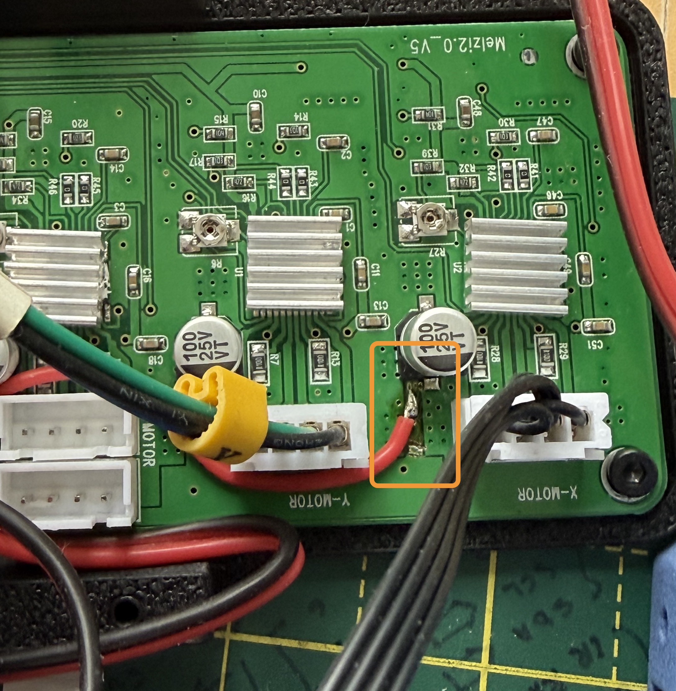
- Control Board (Melzi V2, modified to have 5V stepper voltage on two axes)

- 2x NEMA 17 Stepper Motors

- 8mm rods for the edges (Size can be variable, but need 2x of same length for X axis)

- 2x 6mm rods for the Y axis

- 6 & 8 mm linear bearings

- Idler pulleys

Apart from this plenty of screws, bearings, and belts are needed.

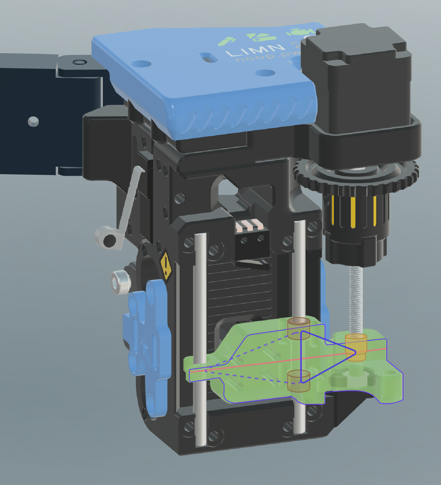
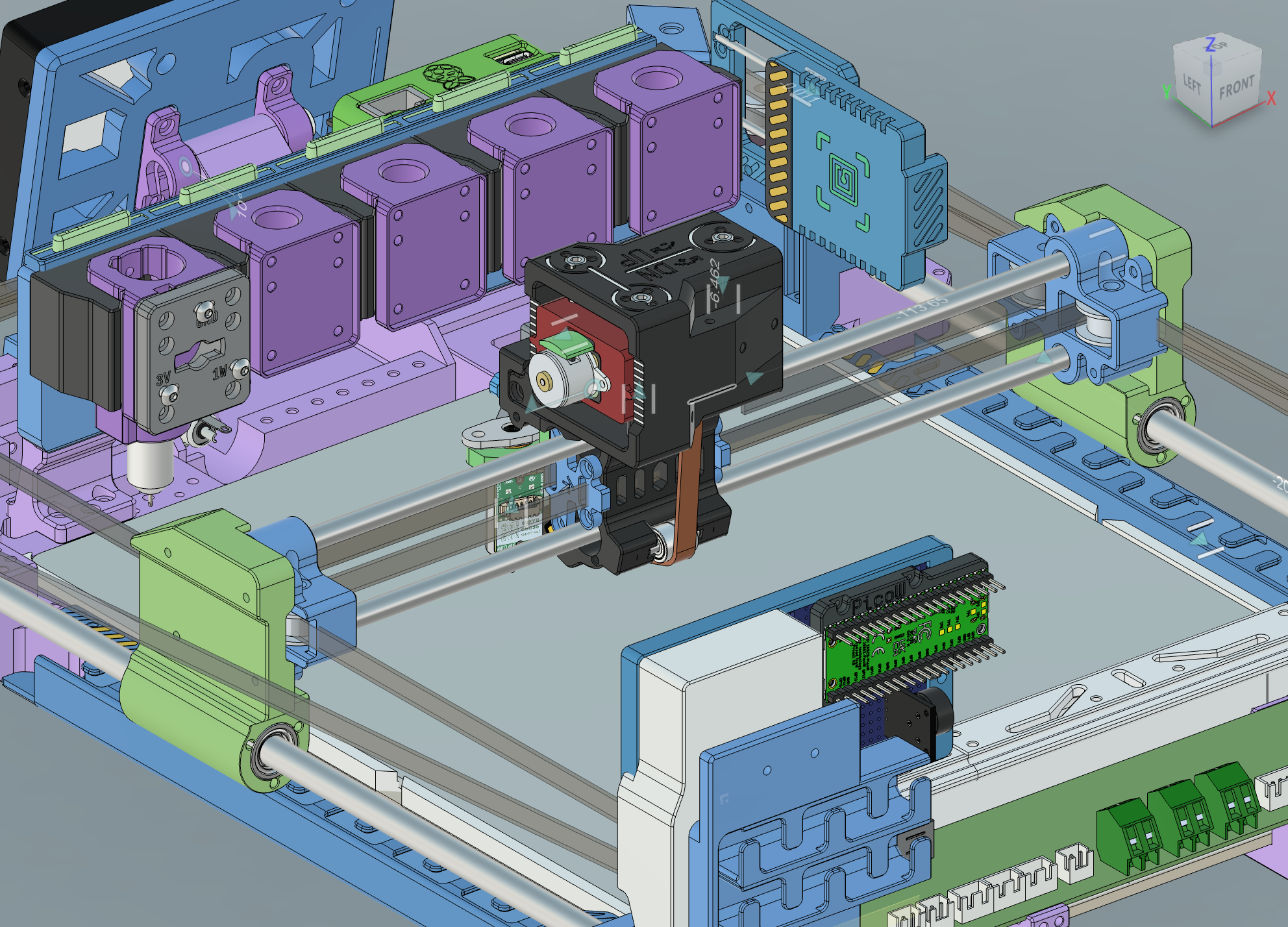
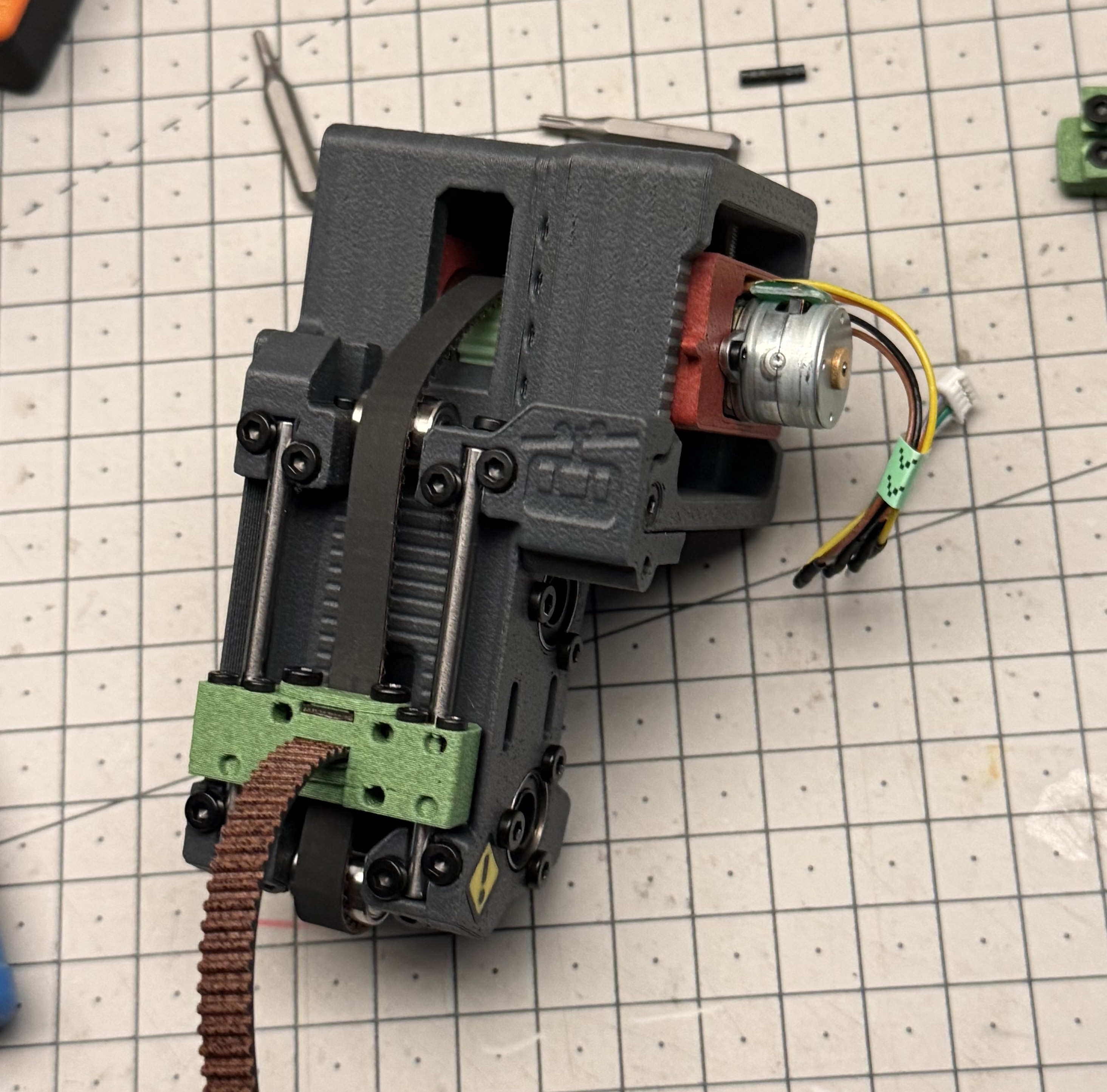
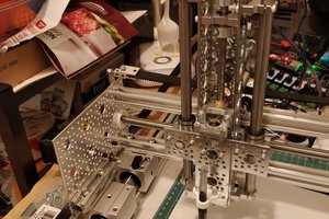
The design uses CoreXY framework. The Z axis is integral to the toolhead.

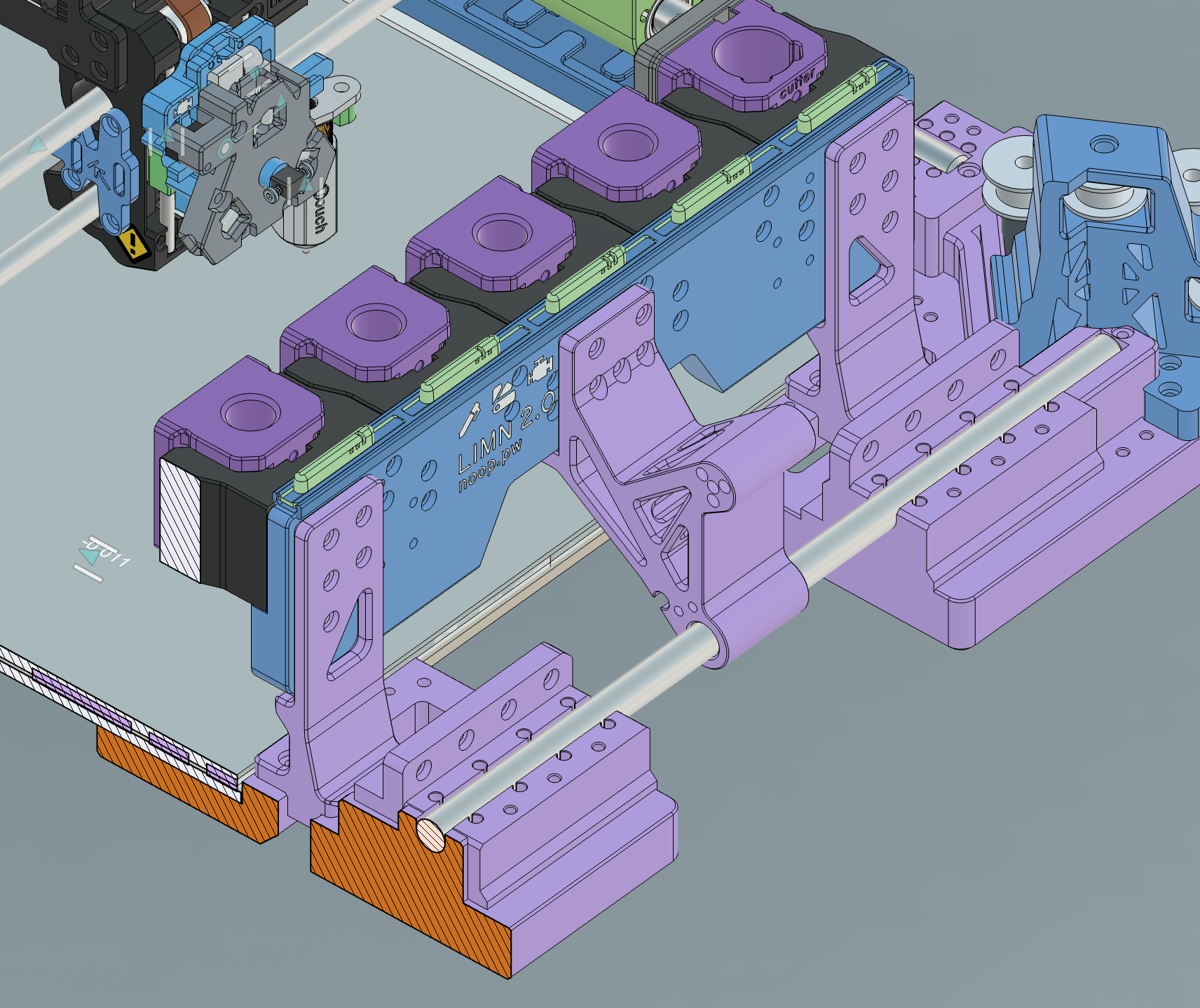
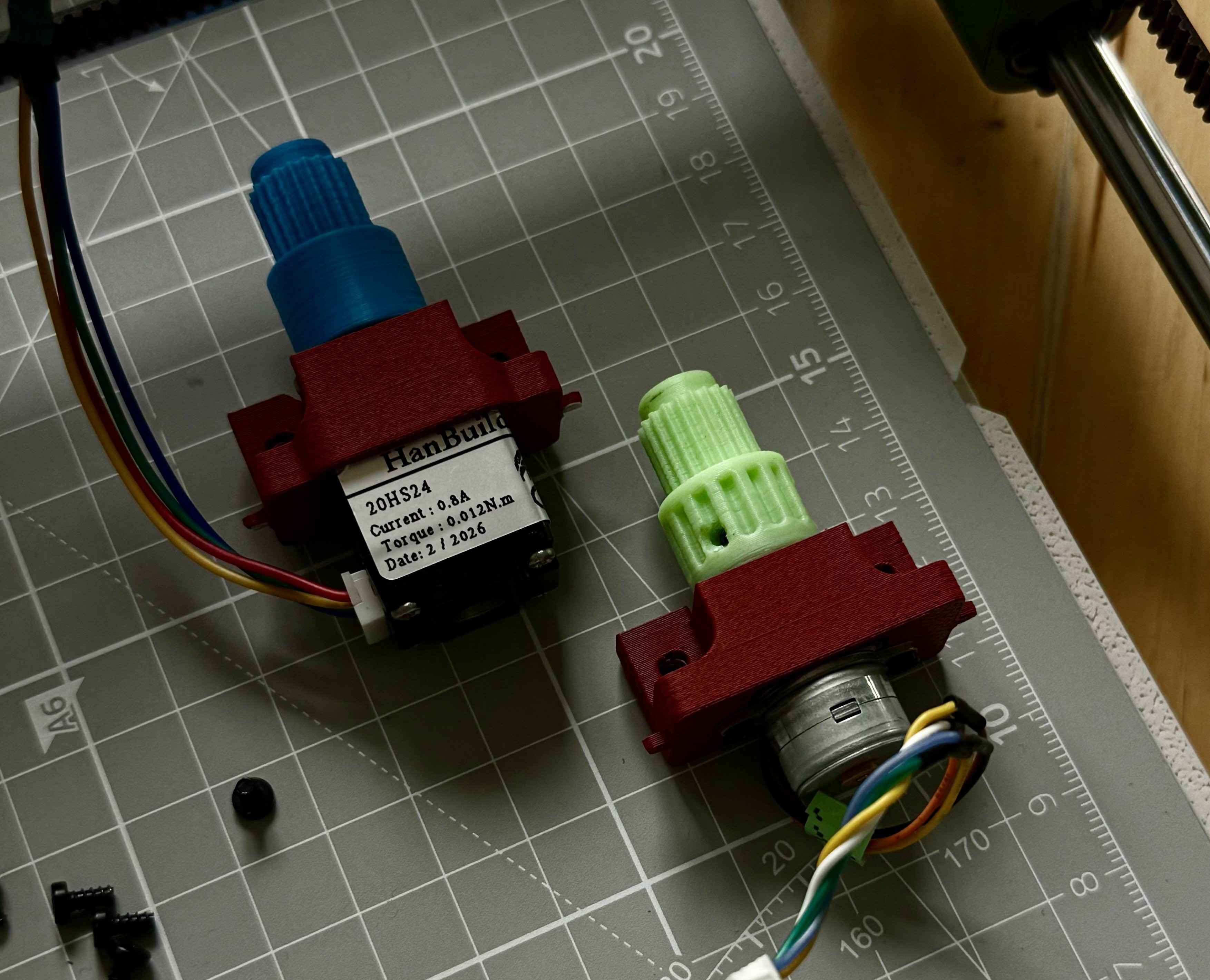
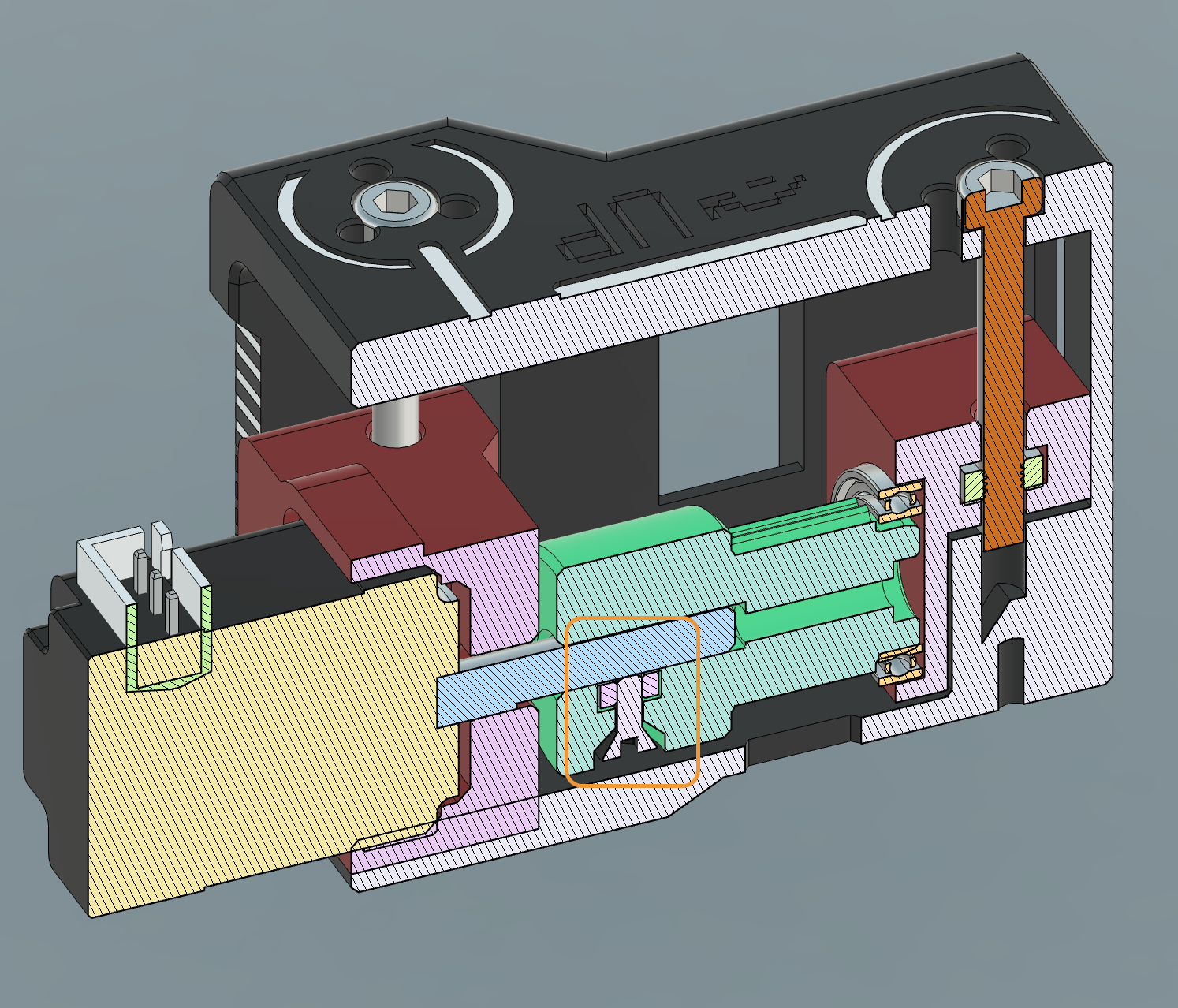
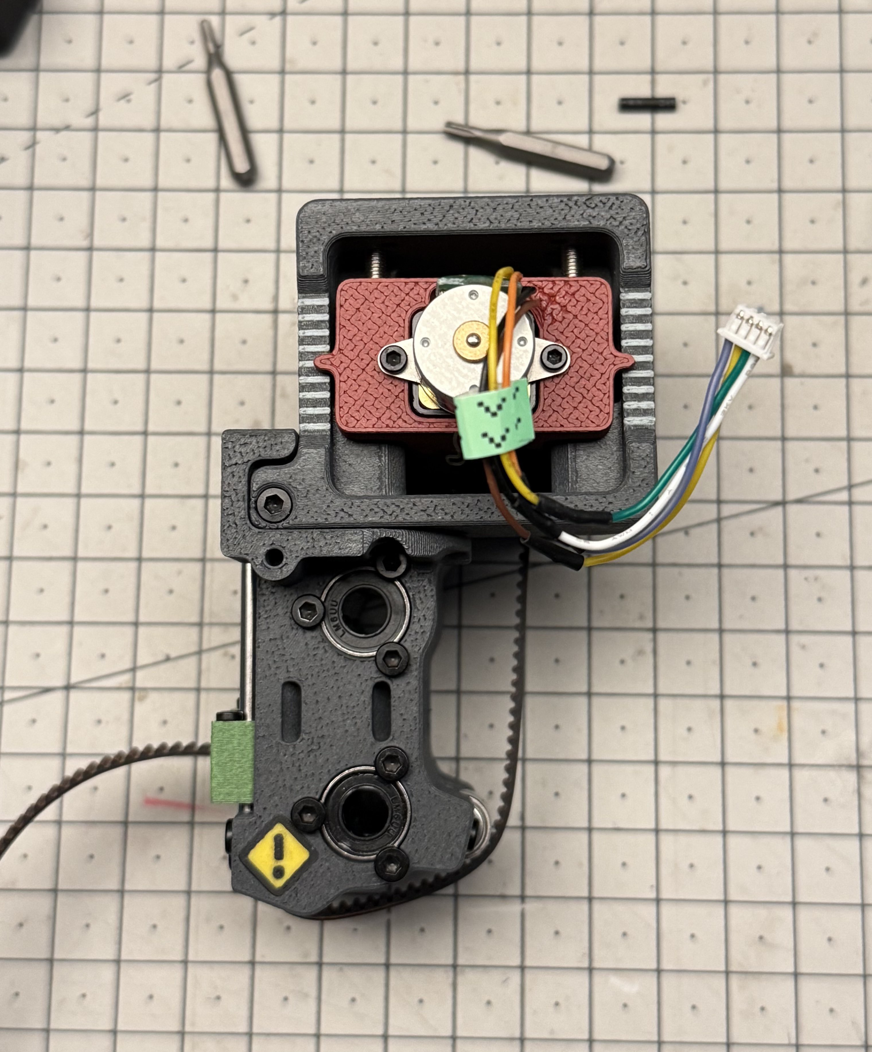
The toolchanger "locking" system uses a tiny linear stepper motor found on Aliexpress, which drives a rack to turn a gear on which the key is mounted. The torque is VERY low and is making it quite challenging to have a successful coupling.

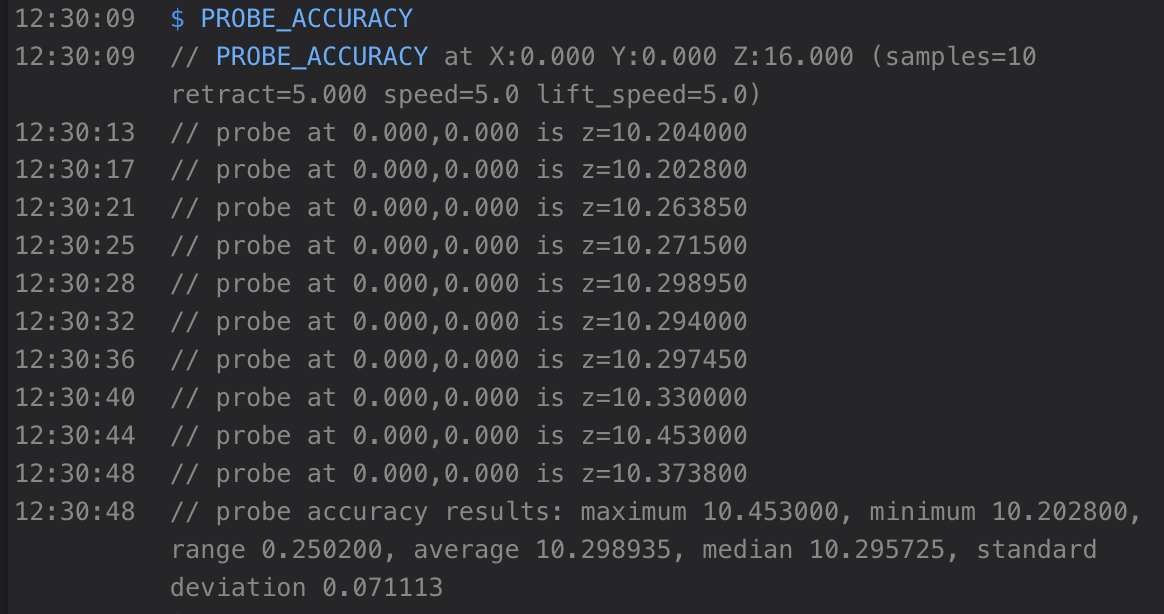
We needed low wobble and low friction, so the rest of the design has to maintain precision for this to work. Also a bit of PTFE lube worked wonders!

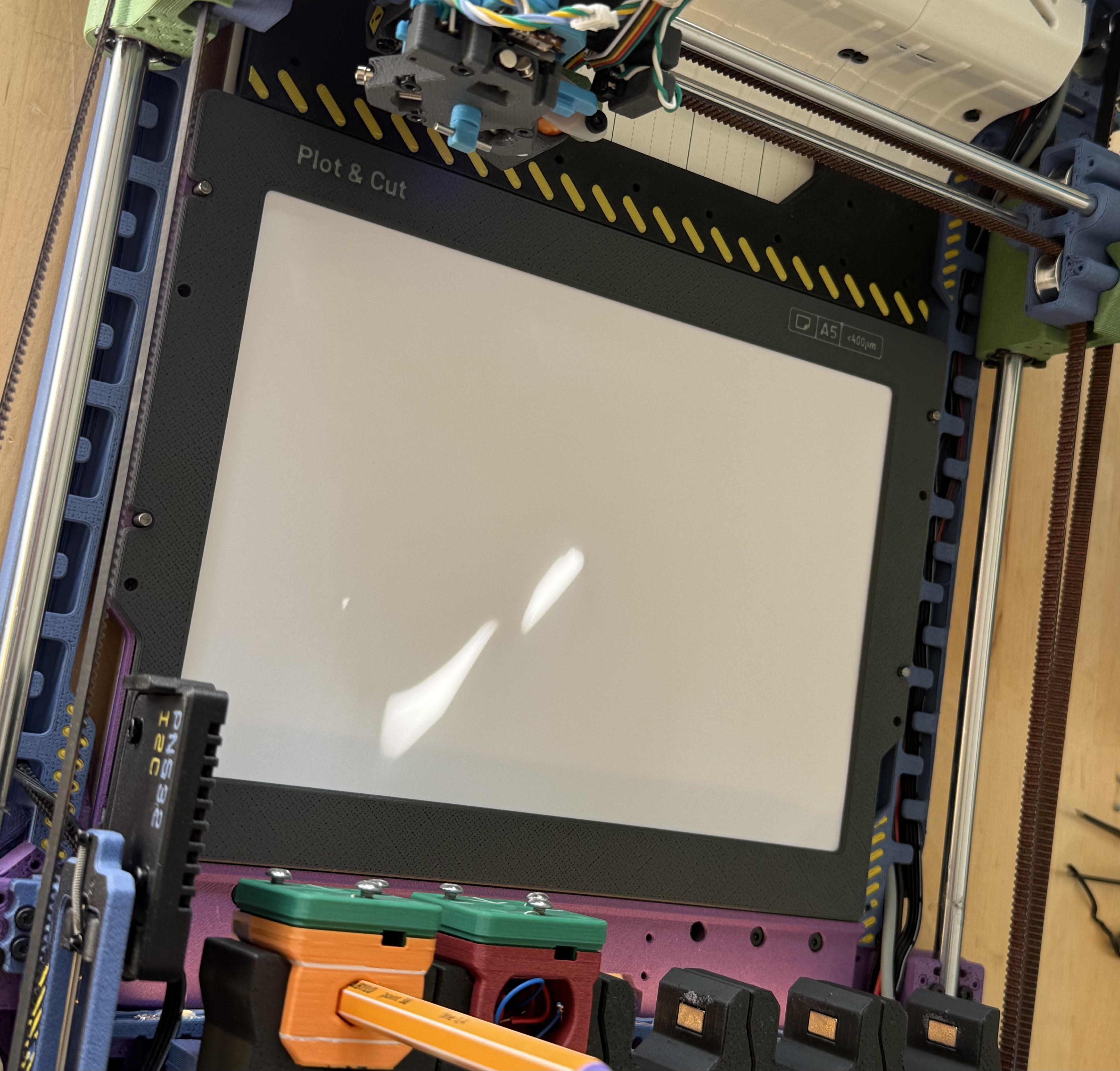
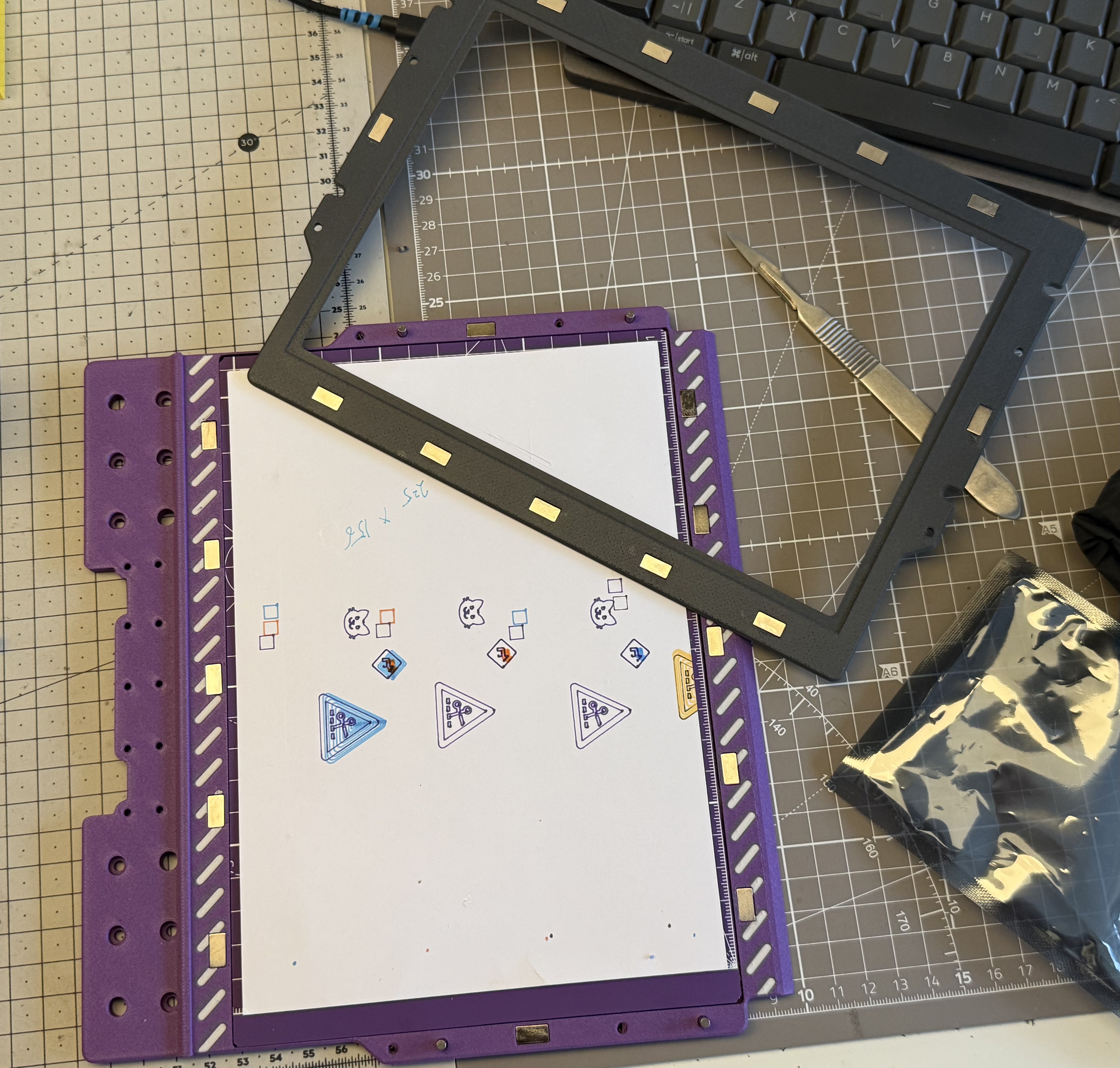
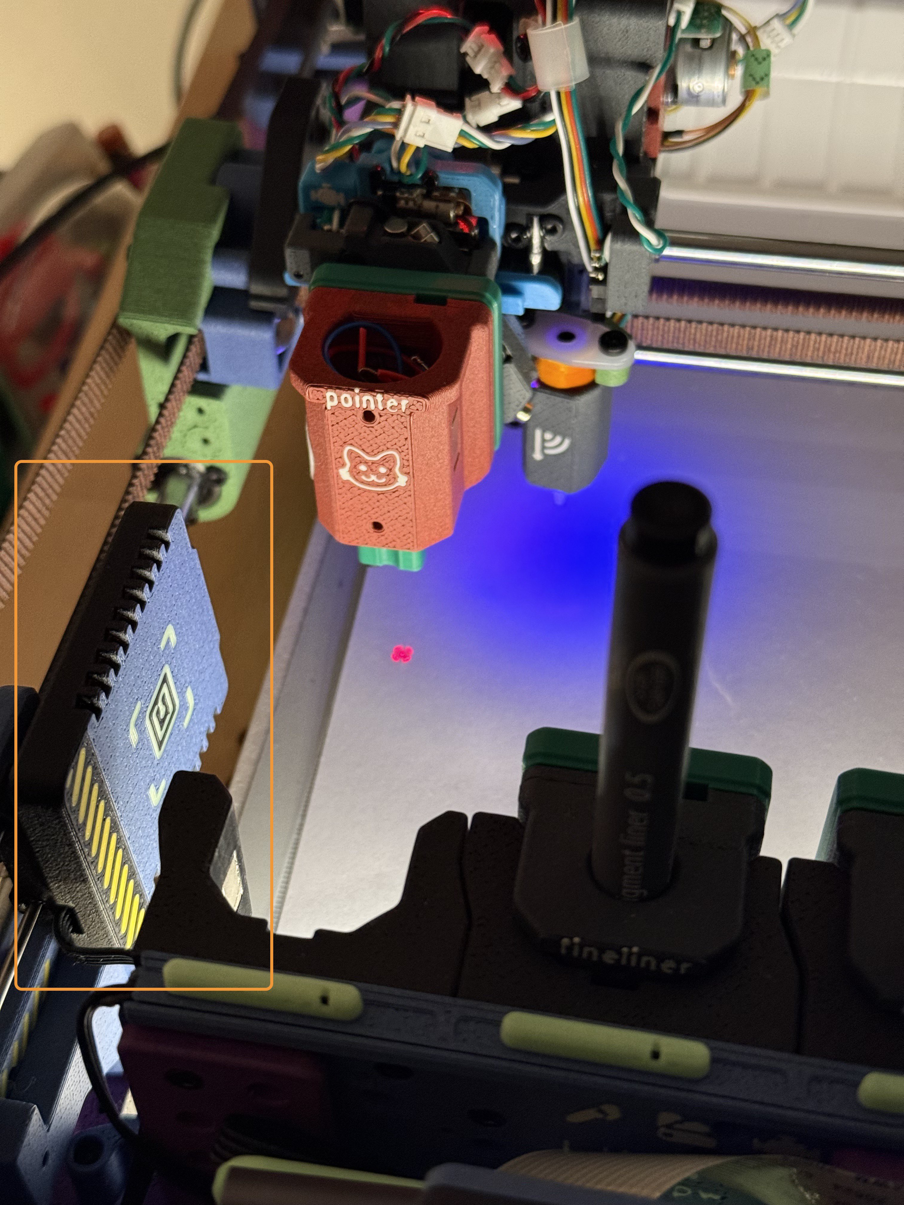
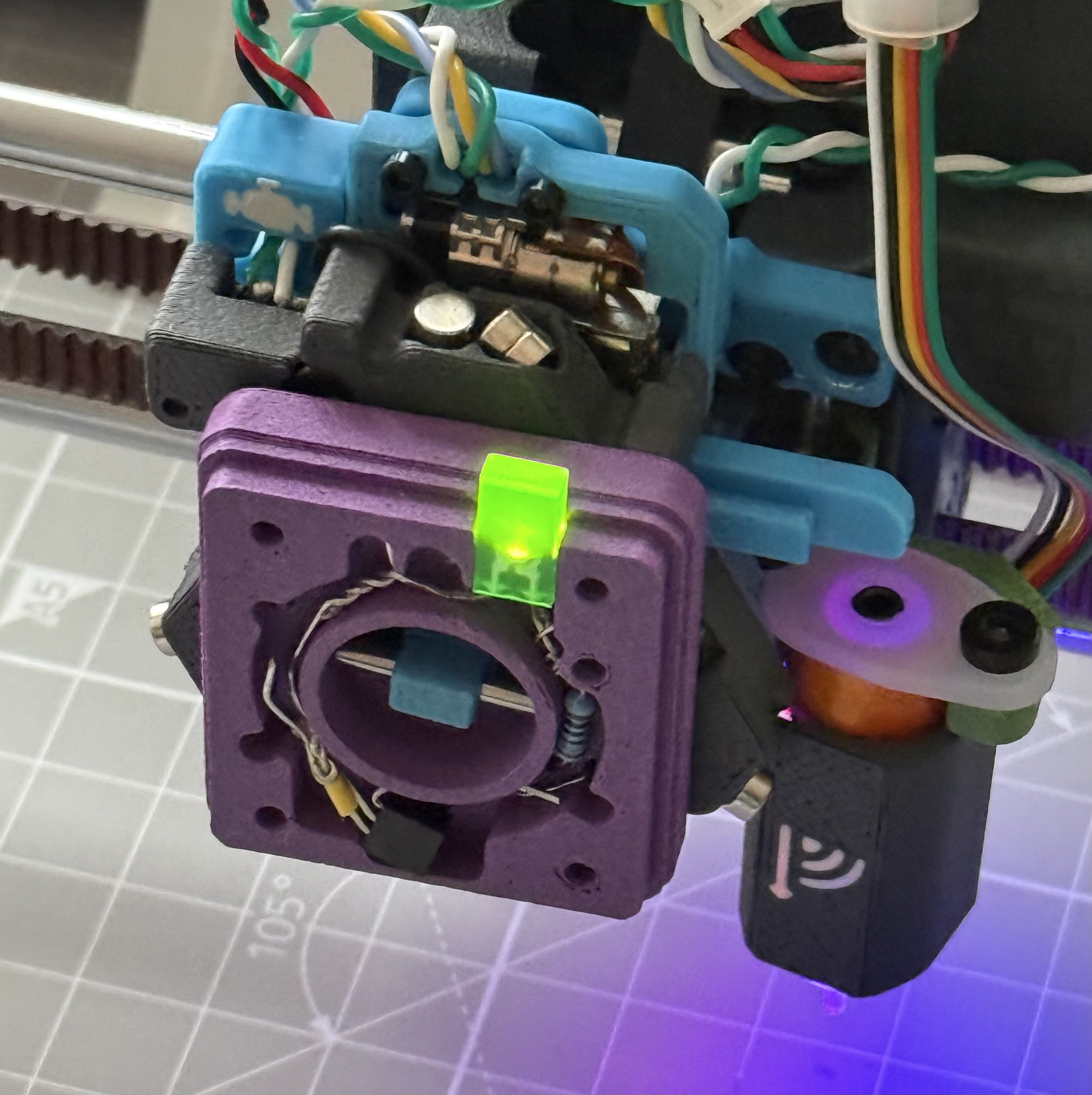
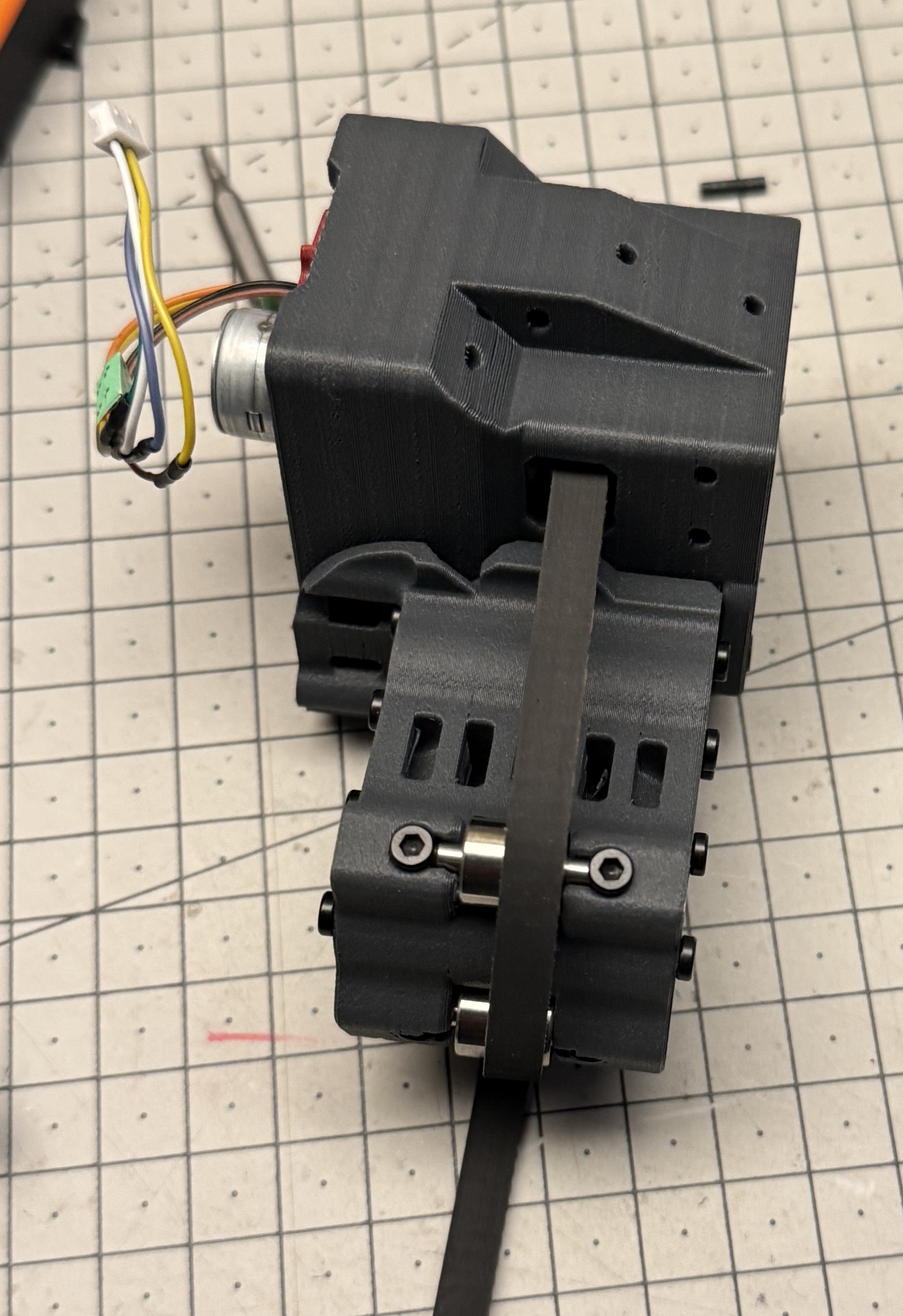
I attach a couple of pics of the toolhead.

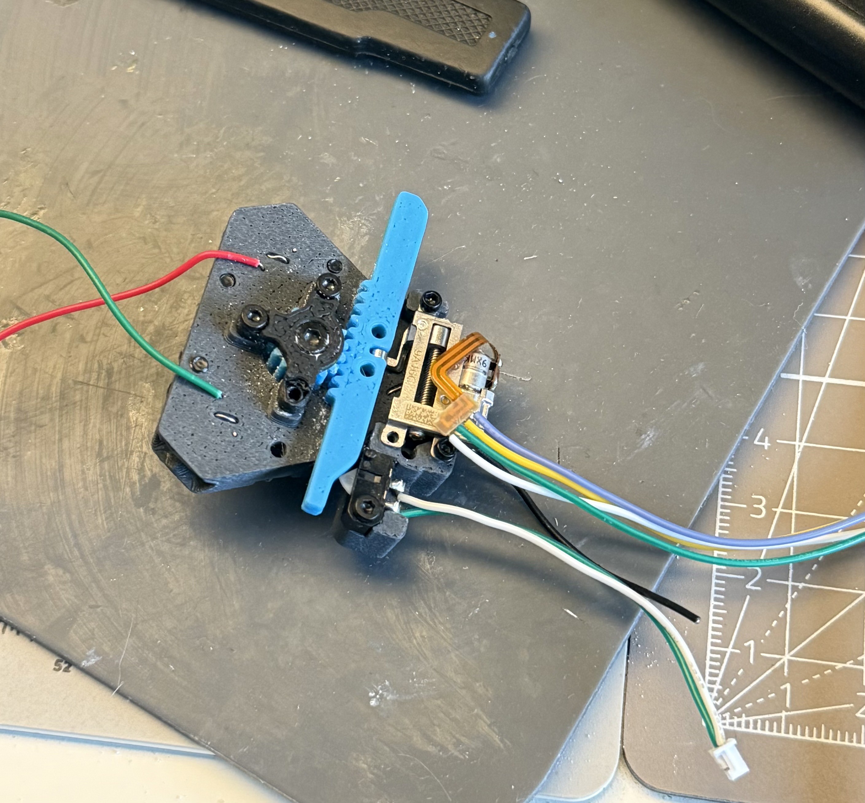
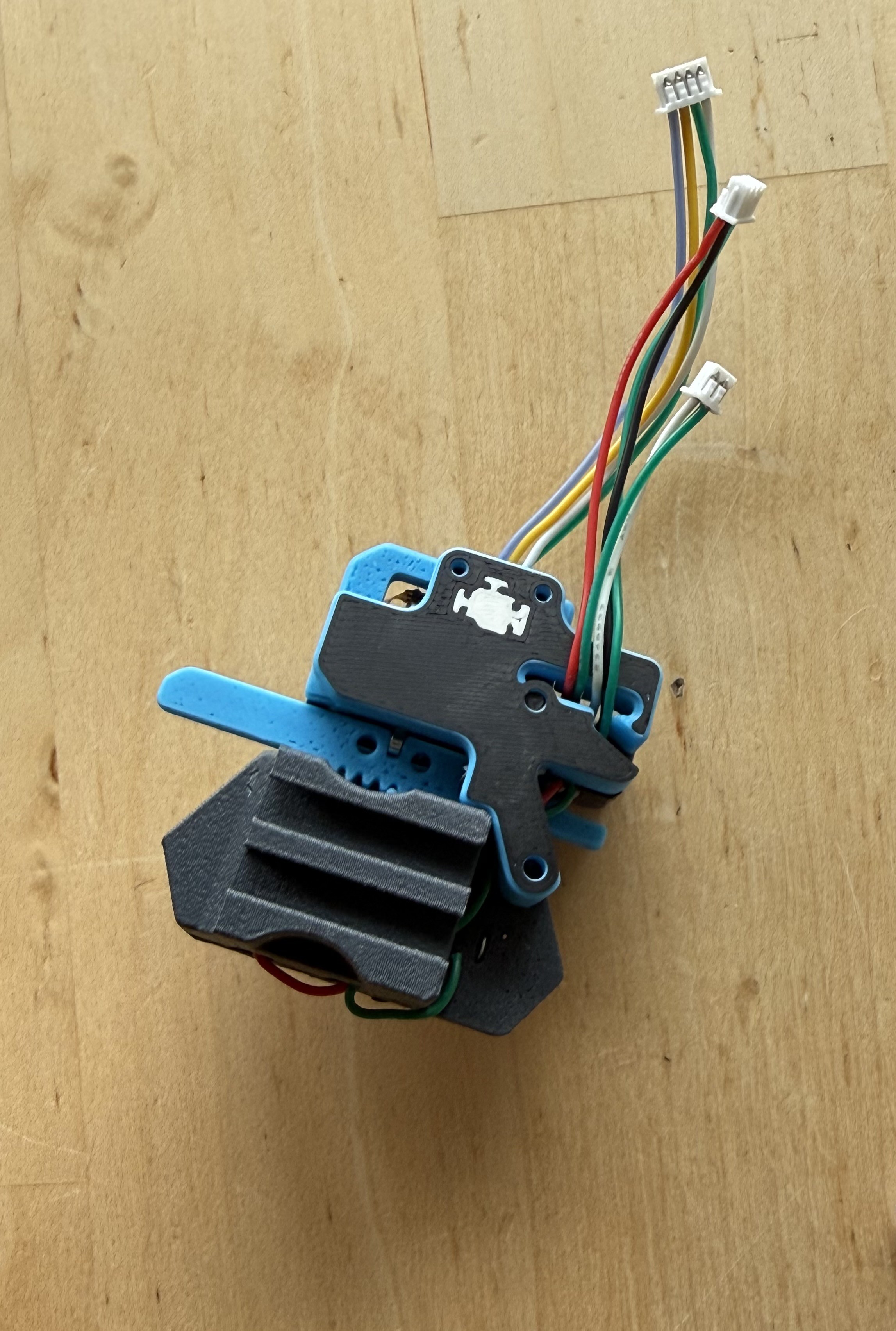
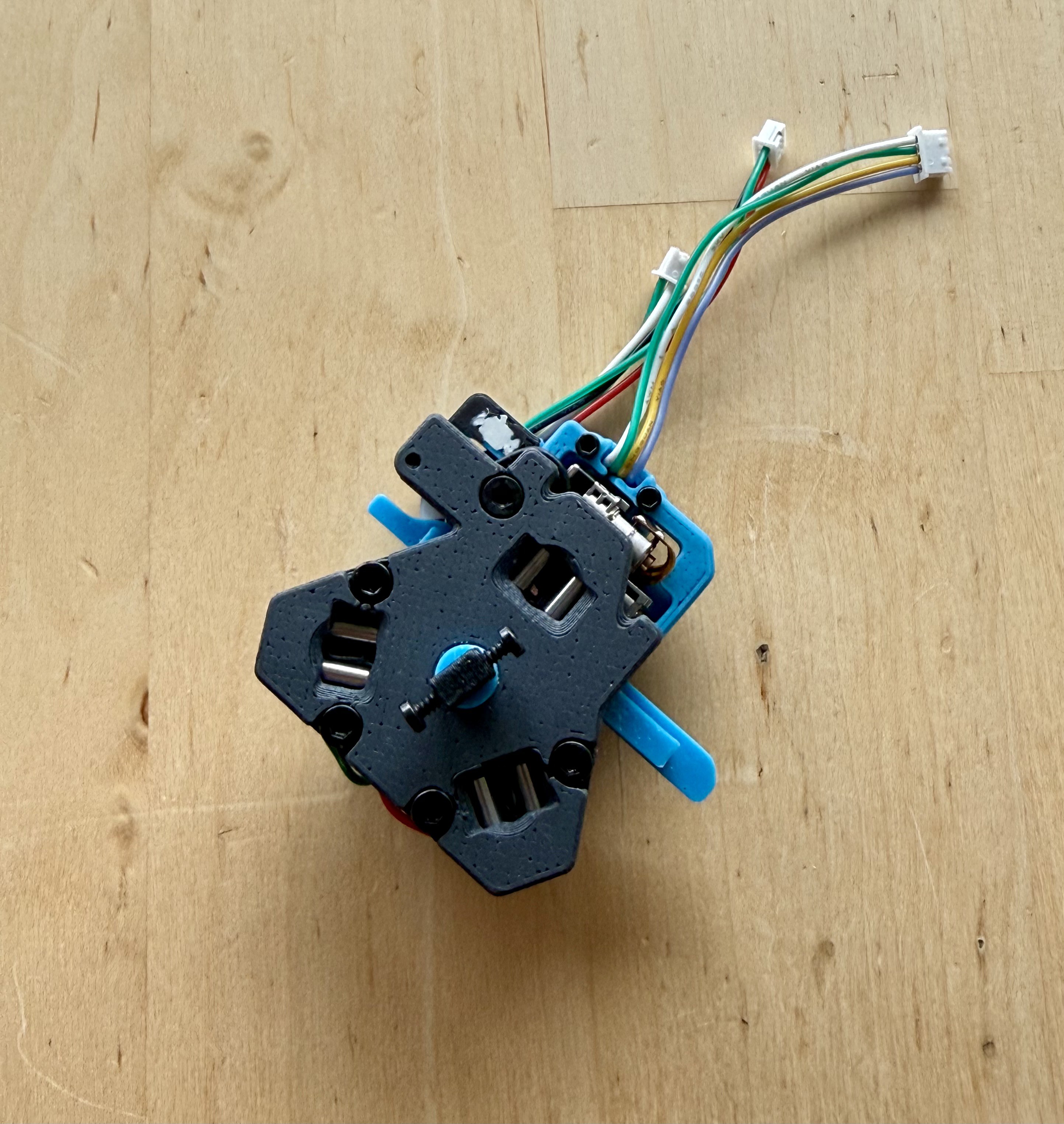
The extra wires are conected to the screws and were intended to power/communicate with the tool in future. I've discovered since that the resistance is too high. Will retry or switch to pogo pins later after eliminating the coupling reliability.

I was mainly inspired by https://www.printables.com/model/137147-ratrig-vcore-3-tool-changer design on Printables, which is where I discovered the term Kinematic coupling (a constraint model for mating parts). 

  • Automatic Tool Alignment in XYZ

    Prashant Sinha5 days ago 0 comments

    Last weekend I spent ~30 minutes calibrating three pens manually. Annoyed, I decided to automate this process as well. For complete pen alignment we need to offset the XYZ coordinates -- the offsets are stored in a RFID tag (more details)

    A Resistive Touch Panel was used to build a new plotter bed. By probing a tool over the panel at several location we can know the three spatial coordinates.

    I used a Cheap Yellow Display (CYD) 2.8" which contains an XPT2046 resistive touch controller and panel. I removed the display entirely and soldered pigtails to four touch panel pins. Then I used another larger resistive panel that I reclaimed from an old car GPS. Magnetic Pogo Pins allow connecting the panel when needed.

    The new bed is 2.5mm thick and magnetic alignement is highly repeatable. I posted a demo video of it in action.

    Hardware

    To connect the touch panel to klipper, I'm currently keeping the CYD in use.

    • The CYD outputs a 3.3V 10ms pulse whenever a touch event is detected.
    • An OR gate built with two NPN transistors combines the BLTouch Probe
      Signal and the touch signal, output of which is used as PROBE_ENDSTOP on klipper.
    • Now, when running Bed Mesh or Probe calibration, the toolhead stops when
      EITHER resistive touch event or BLTouch trigger is detected.
    • This essentially means that basic Z offset calculation work using BLTouch with no changes to klipper.
    • CYD is connected to Klipper Pi over USB.
    • There's a screen protector layer over the panel and the software will implement wear leveling to use the entire panel evenly.

    Software

    The CYD runs a very basic ESPHome firmware. It logs out the XY and Pressure values via serial port and can be read by a Python script. Klipper macros can use CLI command to run the script when probing to read the coordinates.

    A PROBE_TOOLS macro will automate the whole process:

    1. Partial BLTouch bed mesh over the touch panel.
    2. Docks `reference tool` (T0) and probe at 4 locations. Stores the coordinates and scaling factor.
    3. Following steps are repeated from tool T1 to T4:
      1. Dock Tool
      2. Slow Probe to find tool Z offset
      3. Fast Probe at 4 locations
      4. Calculate XYZ offset from reference pen
      5. Write the offset to pen's RFID tag
      6. Undock Tool
    4. Partial bed mesh on paper area (A6 size).
    5. Repeat from T0 to T4:
      1. Dock Tool (also reads the tag)
      2. Draw alignment pattern
      3. Undock
    6. User/Camera confirmation

    Roughly 10 units of displacement on the touchscreen corresponds to 1-2mm toolhead movement, in my observation. I'll work on alignment script next, given that I seem to have all the required parameters about tools available.

    Github repo will be updated soon containing the config changes. 

    PS: The screen that comes with the CYD is also sufficient, I just had some extra available. It was slightly thicker as well since I couldn't easily remove the display layer.

  • Applying Tool Parameters, Tethered tools

    Prashant Sinha05/01/2026 at 20:53 0 comments

    I finally got around to implementing the initial version of tool alignment. As I mentioned in a previous post, it'd require extra effort to align each pen manually at true zero. Instead we opted for an RFID tag affixed to the tools. The tag currently contains XYZ offsets and a tool identifier. In future for tools such as paint markers we can also store attributes to inform the plotter to purge the pen at a given interval, or for cutting tools, the blade angle and cutting depth.

    To read the tag and apply tool parameters during print run on Klipper, I came up with a method as described below:

    1. Reading Tool Data when docking

    A klipper module is created that allows us to execute arbitrary shell commands. The output of this command would contain the "result" enclosed in a known heredoc style pattern. The gcode can read this result using the `printer` variable. Then we can apply the XYZ offset using `SET_GCODE_OFFSET` command. Of course this is a potential security vulnerability if we run unknown gcode, but something to be improved later (quite easily).

    [gcode_macro _RFID_HOME]
    gcode:
      G1 X130
      G1 Y3
      G1 Z7
      M400
    
    [gcode_macro RFID_READ]
    gcode:
      # Home to Reading Position
      _RFID_HOME
      EXECUTE_AND_STORE COMMAND="/home/pi/.local/bin/uv run --directory /home/pi/limn rfid.py read-tag"
      M400
      APPLY_RFID_DATA
    
    [gcode_macro APPLY_RFID_DATA]
    gcode:
      {% set output_buff = printer["shell_output sh_output_buffer"].output %}
      {% if "||" not in output_buff %}
        # Do nothing
        M118 No tag found.
      {% else %}
        {% set comps = output_buff.split('||') %}
        SAVE_VARIABLE VARIABLE=tool_offset_x VALUE={comps[0]}
        SAVE_VARIABLE VARIABLE=tool_offset_y VALUE={comps[1]}
        SAVE_VARIABLE VARIABLE=tool_offset_z VALUE={comps[2]}
        SAVE_VARIABLE VARIABLE=tool_name VALUE='"{comps[3]}"'
        M118 Stored offsets for tool.
      {% endif %}

    In short, we use the saved variables to pass the tool information between macros. 

    The potential security issue stems from the fact that if an attacker is aware of `EXECUTE_AND_STORE` command, they are able to add it within their own crafted Gcode. So caution should be taken (as always) when plotting unknown gcode.

    2. Applying tool offsets

    We override move commands (G1, G2, G3) so that when instructed, we apply the tool offsets before moving. Any moves not containing `ALIGN1` parameter would not be affected by gcode offset -- this is a feature, as we can choose to only align certain moves.

    [gcode_macro _APPLY_OFFSETS]
    gcode:
      {% set align = params.ALIGN|int %}
      {% set svv = printer.save_variables.variables %}
      {% set offset_x = svv.tool_offset_x|default(0)|int %}
      {% set offset_y = svv.tool_offset_y|default(0)|int %}
      {% set offset_z = svv.tool_offset_z|default(0)|int %}
    
      {% if align == 1 %}
        SET_GCODE_OFFSET X={offset_x} Y={offset_y} Z={offset_z}
      {% else %}
        SET_GCODE_OFFSET X=0 Y=0 Z=0
      {% endif %}
    
    [gcode_macro G1]
    rename_existing: G1.1 # Rename the existing G1 command to G1.1
    gcode:
      {% set p_x = ' X' ~ params.X if 'X' in params else '' %} # Extract only the move commands we care about.
      {% set p_y = ' Y' ~ params.Y if 'Y' in params else '' %}
      {% set p_z = ' Z' ~ params.Z if 'Z' in params else '' %}
      {% set p_f = ' F' ~ params.F if 'F' in params else '' %}
      {% set act = params.ACT|int if 'ACT' in params else 0 %}
      {% set align = params.ALIGN if 'ALIGN' in params else 0 %}
    
      _APPLY_OFFSETS ALIGN={align}
      {% if act == 1 %}
        # PEN DOWN
        {% set p_z = " Z0.2" %}
      {% elif act == 2 %}
        # PEN UP
        {% set p_z = " Z5" %}
      {% elif act == 3 %}
        # TRAVEL
        {% set p_z = " Z7" %}
      {% endif %}
      {% set ps = p_x + p_y + p_z + p_f %}
      G1.1 {ps}
    

    3. Applying tool offsets only when drawing (and other moves)

    Since the toolhead interacts with the machine physically (eg. docking, rfid read) we need to selectively apply the offsets only when it's needed. Currently the only place it's needed is when drawing. Therefore I modified slicer config to append parameter `ALIGN` on each travel and draw moves. If a tool doesn't specify any...

    Read more »

  • New Z axis, Plotter Bed, STEP Files

    Prashant Sinha04/21/2026 at 14:36 0 comments

    I spent some time reflecting and then decided to actually fix the backlash issue in the Z axis. My initial tests showed that the NEMA 8 motor would be good enough for a lead-screw driven axis. A 35mm M3 bolt was attached to a bracket with a nut and fixed with thread-locker. Then the "lead screw" is fixed to the motor using a coupler.


    The lead-screw, which drives the Z axis, is placed on one side. This posed a challenge because the "rider" would tilt up/down and jam. I looked around at slide mechanisms, and noticed that many optical drives a common layout -- the rider is kept level through triangular geometry. The following shows the current slider layout:


    This works surprisingly well, although is a bit slower than belted axis. I'd need to recalibrate the tool dock and also find the correct rotation-distance. 

    Update: I'm reasonably close to correct value: 0.03 mm/rotation (the value is explained by the fact that I'm using no microstepping on a driver hard-wired for 16 microsteps. I can't use microstepping because the AVR MCU can't generate steps fast enough.) The probe accuracy is reasonably better:


    ----

    To keep the paper flat I designed a magnetic bed system adapted for A5 paper size. I believe it'd be good enough to cut/score paper as well.

    ----

    Checkpoint 1: I've published all the current design files in the GitHub repository. The Fusion360 file barely fits under 100MB (zipped) and is fully articulated. Also uploaded the STEP file.

    The printer config is no longer valid and I'll update them later. 

    This took about four months of effort and I'm pleased with the results so far. I think the toolhead could be easily adapted to fit on other CoreXY frames as well, and hence I've grouped it (and others) together in the design files. Majority of the components were sourced from Bambu store and AliExpress.

    I'll also post the files to Printables next month along with some instructions.

    Link to Files: https://github.com/prashnts/limn/tree/master/step

  • Interactive Plotting

    Prashant Sinha04/15/2026 at 21:15 0 comments

    I posted a quick video showing how I'm using the plotter currently. It's far from ideal but also quite efficient. Basically just dragging SVGs from Sketch to the slicer. As long as the paper doesn't move we can keep plotting at different areas.


    Apart from pen alignment, the core toolchanging part seems to work well now. Here are some plots I've done lately: 

    > An image vectorized in Inkscape, 0.05mm


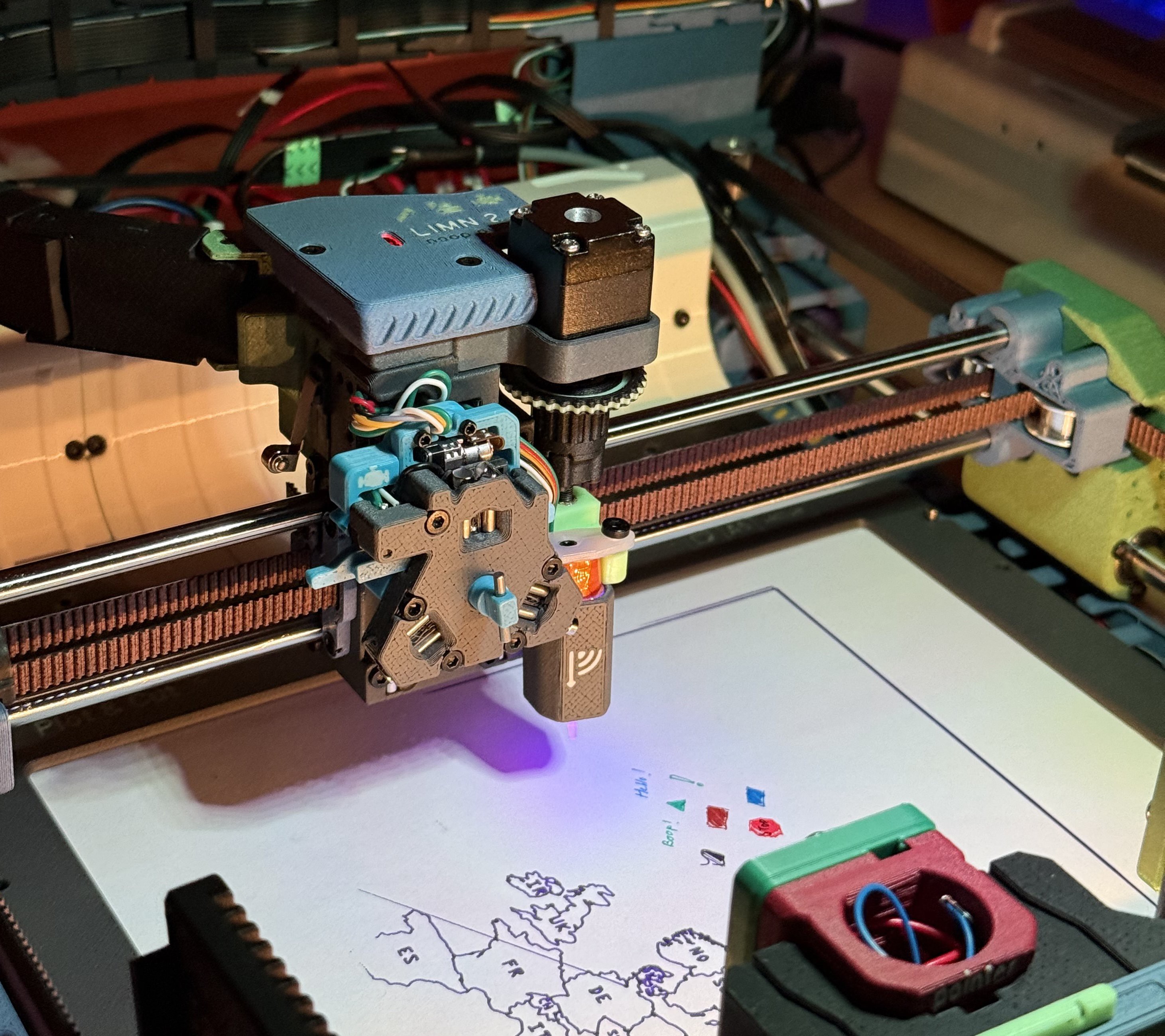
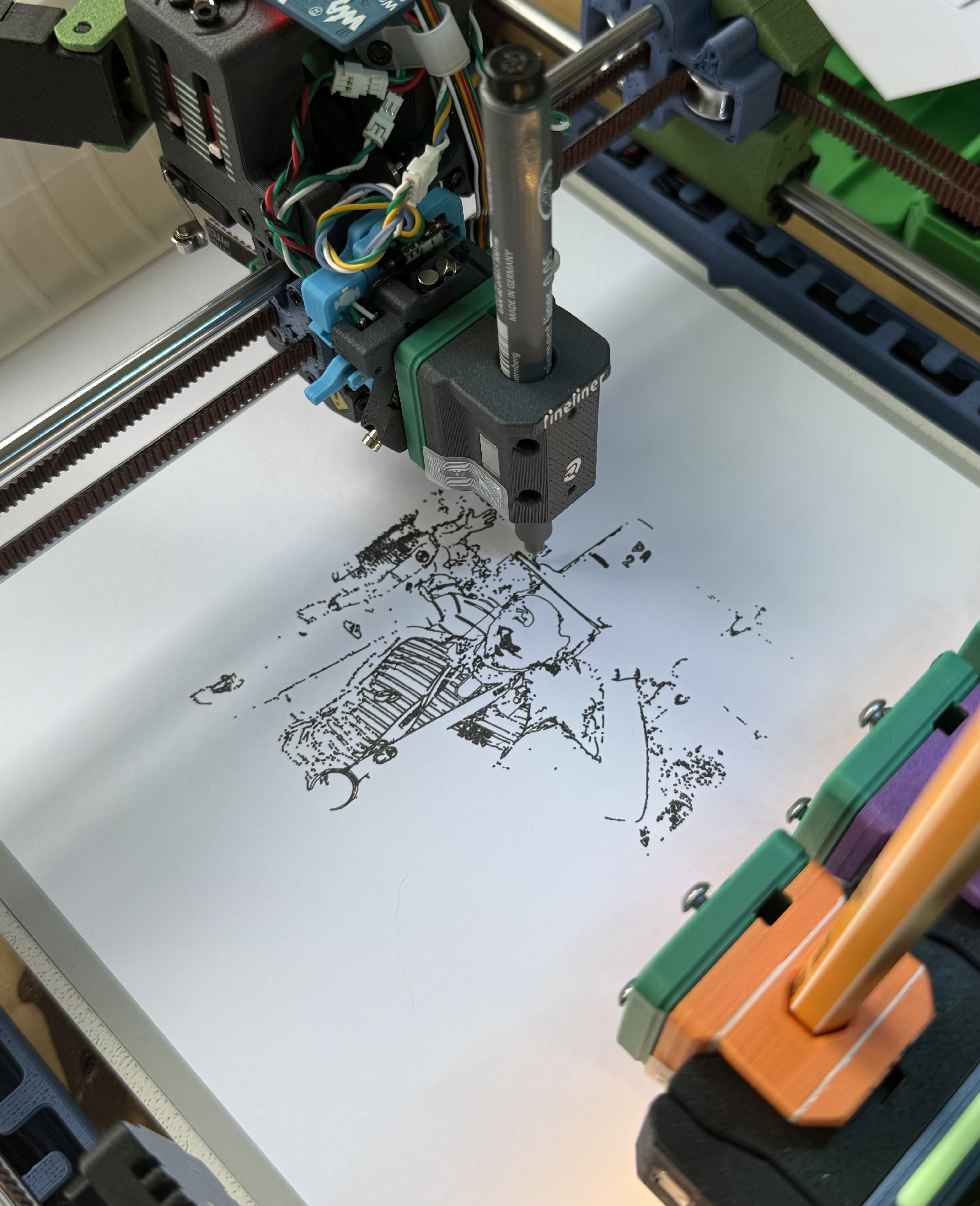
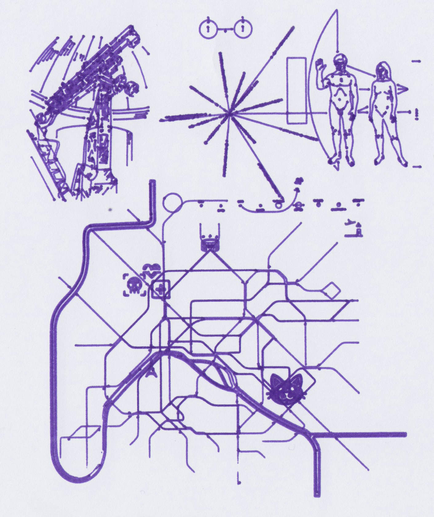
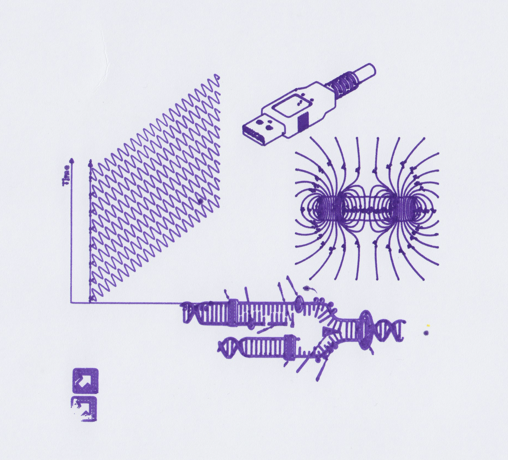
    > Drawings from Wikimedia Commons, 0.7mm
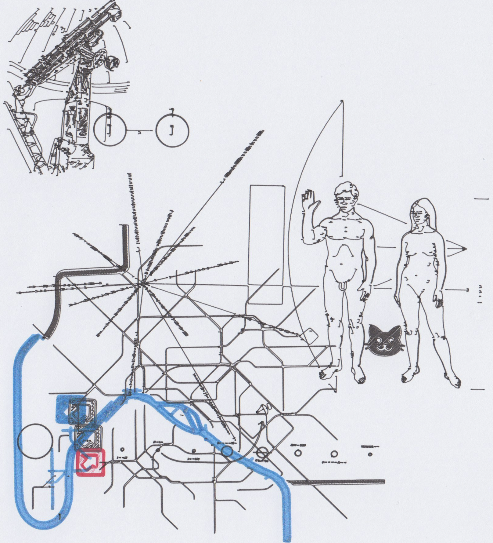
    > Pioneer Plaque, Paris Metro map (using toolchanger, misaligned). 0.05mm

    The paper curled at certain points but overall I'm happy with the results.

    > Paris Metro, Pioneer Plaque, Telescope. 0.7mm

  • RFID Read, Source available on GitHub

    Prashant Sinha04/11/2026 at 15:42 0 comments

    I posted a screencast where the plotter scans RFID tags on the tools. Still need to find out how to use the values read.

    Additionally, I was finally able to clean up a bit the klipper side of things. In the Limn repo I've published the current printer/toolchanger/rfid config. It's under MIT license. The README explains the contents.

    Link to Github

    This is my first time configuring klipper, so I'd be keen to know what could be done better!

  • Under the hood

    Prashant Sinha04/10/2026 at 19:33 0 comments

    The plotter is designed to be scalable. Four components in each corners mate with variable lengths of rods/belts/base.

    A hard MDF board and the four steel rods on the edges together form a sufficiently rigid and square frame. I got the rods and bearings from a Tronxy 3D Printer Kit, as well as the driver PCB and XY Stepper Motors.

    The driver board uses 12V, and has 4 A4982 driver chips. Z axis is configured to drive dual Z axis motors so we have a different pinout here for the motors.

    I'd noticed the small SRM1509 and Linear motors get too hot on 12V regardless of proper VREF, so I cut the 12V trace and supplied external 5V to Z and K (the toolhead lock) axis drivers.


    When the belts are tensioned the frame is pulled inwards along the belt direction, which reduces the wobble. However it will likely deform when lifted in the current setup. There is not much to do unless we switch to a metal frame.

    The tool dock however needed special consideration as we need it to not move and survive the toolhead crashing into it. To keep it positioned the brackets (shown below) mate with a steel rod, and rest on the base. The middle one also acts as a hinge for the LCD.


    --

    I'm quite close to finishing the design. I've built a 1:1 model in Fusion360, and would just like to give a shout to amazing people on GrabCAD and Printables (and elsewhere) for sharing their models. I'll be posting the STEP files on Printables (about a week or so). There are many parts, with some parts such as the K axis requiring special considerations (and it's pretty specific to the hardware I had at hand) so there's a bit of work left to do to documenting them. Almost all parts print without supports. 


  • Detecting Tools, Tool Parameters, "Slicing"

    Prashant Sinha04/09/2026 at 12:22 0 comments

    The tool docking mechanism relies on Maxwell Coupling for repeatability, however this repeatability only holds per tool. As such, different pens will land at varying positions on the paper for the same coordinate.

    My current understanding is that it will be too much effort to precisely align each tool, and rather it'd be easier to calibrate each tool against a reference tool (ideally the sharpest pen). Hence we need a way to configure the tool parameters (`{offset_x, offset_y, offset_z, depth...}`). 

    For the sake of simplicity it'd be good that the printer handles this at runtime. Any print file could be printed by any tool/tools. 

    I really did not want to reinvent any more wheels, so I stuck to PrusaSlicer. A new printer config, with custom gcode templates, multi-extruder toolhead, and some regex susbtitution later I can now drag an SVG file in the slicer, and generate the exact GCODE that klipper is expecting.

    Pen Up and Down motion is achieved by replacing `retraction` events. I chose to keep raw Z values here, and change Z-offset on klipper instead, so that the travel moves reflect actual pen moves in the preview. Similarly extrusions are kept only to have something in the preview, but are ignored by G1 macro.

    The slicer emits T0..T4 commands for each tool change. On klipper side custom macros translate these commands to actual movement.

    I still haven't figured out varying nozzle sizes while slicing but it should be possible. 


    Back to detecting tools: A basic detection can be done by physical contact with the coupling surface -- on the tool's side we can bridge two screws with a wire. I'm aware of 1Wire EEPROM being a thing but did not find any to buy. There seems to be several Spool detecting projects, such as OpenSpools, which can use RFID readers to detect the spools. We could use something like that.

    To set the parameters there's now a spring-loaded-retractable RFID sensor mounted near the first tool. It can be slid back by the Y axis. 

    (I did not realize that I wired the PN532 with I2C, but OpenSpools needs SPI connection. I'm too lazy to take it out so I'll likely have to figure out an alternative on this.)

    On the tools we stick a tag and the docking macro will eventually use the sensor for tool parameters. 

  • NEMA 8: No Go & Backlash Correction

    Prashant Sinha04/03/2026 at 15:46 0 comments

    I received the AliExpress NEMA 8 motors yesterday and replaced the SRM1509 for a test. After tightening the belts I can turn the axis manually but the stepper just buzzes. I tried upping the stepper current till 0.8A but I could stop the shaft with my fingers. Oh well. I went back to the previous motor.

    I wanted to make a note about the pulleys. Normally even if you make the shaft hole good size the pulley would not engage and the little flex it has will allow it to turn. I figured a good way to prevent this is by embedded nuts. Essentially a nut on the flat surface of the shaft, and a screw. 

    Since for now we have to live with the gear play I attempted correcting the backlash in software. Klipper allows you to override any macros, including G1, and with a macro variable one can keep track of the direction the motor was going in previously. If we are about to go in opposite direction then extra motor movement can correct for backlash IF it is stable (it is in my case). Only problem is that BED_CALIBRATE does not seem to be using a G1 command so the bed mesh is not corrected.

    For plotting without a bed mesh the backlash is not really a big deal. With bed mesh we need to just be careful to not overshoot the end positions on the axis. I haven't found a clean way to do this yet, but I'm looking at /extras dir in klipper right now.

    gcode_macro G1]
    rename_existing: G1.1 # Rename the existing G1 command to G1.1
    gcode:
      {% set is_abs = printer.gcode_move.absolute_coordinates %}
      {% set curr_z = printer.toolhead.position.z %}
      {% set param_z = params.Z|default(-42)|float %}
      {% set new_z = 0 %}
      {% if 'Z' in params %}
        {% set next_z = param_z if is_abs else (curr_z + param_z) %}
        {% set delta = next_z - curr_z %}
        {% set direction = (delta / delta|abs) if delta != 0 else last_dir %}
        {% set backlash = 1.8 if direction != last_dir else 0  %}
        {% set correction = backlash * direction %}
        SET_GCODE_VARIABLE MACRO=G1 VARIABLE=last_dir VALUE={direction}
        {% if correction %}
          {% set step_to = correction if not is_abs else (curr_z + correction) %}
          # SET_KINEMATIC_POSITION Z={curr_z - correction} SET_HOMED=''
          G92 Z{curr_z - correction}
          G1.1 Z{step_to}
          # SET_KINEMATIC_POSITION Z={curr_z} SET_HOMED=''
          G92 Z{curr_z}
          M118 Corrected: Backlash: {backlash} Direction: {direction}
        {% endif %}
      {% endif %}
      {% set p_x = ' X' ~ params.X if 'X' in params else '' %}
      {% set p_y = ' Y' ~ params.Y if 'Y' in params else '' %}
      {% set p_z = ' Z' ~ params.Z if 'Z' in params else '' %}
      {% set p_f = ' F' ~ params.F if 'F' in params else '' %}
      {% set ps = p_x + p_y + p_z + p_f %}
      G1.1 {ps}
    variable_last_dir: 1

    PS: The 3-point coupling seems to be good enough to pass some electricity, finally! 

  • Z Axis & Toolhead

    Prashant Sinha04/01/2026 at 18:50 0 comments

    For a plotter we do not really need large Z axis movement. Initial iterations used a MG14 servo motor for Pen Up/Pen Down motion. It worked but was loud, imprecise, and limited to flat bed.

    I found that SRM1509 stepper motors were just strong enough while being small and are what in use currently. These use a gearbox so some trial and error yielded a close but incorrect Z scaling. Additionally there is significant play due to gears and I had to account for the backlash.

    The motor module is designed separately so can be changed for a different system later. I plan to switch to NEMA8/NEMA11 motors soon. Currently the belt tension is achieved through three bolts that lift the entire motor and GT2 pulley assembly. 

    For the motion system 3mm/5cm dowels and bushings are used. Belt rides on 603ZZ bearings. When tensioned, the motor module and Y axis "rider" are rigid. Weighs about 250g!

    Attached some pictures.

  • First Steps

    Prashant Sinha03/31/2026 at 09:03 0 comments

    Magnets was the answer, as it turns out. For locking the tool, good alignment is necessary. I had planned for, but forgotten to put, magnets on the coupling screws to help the tool positioning. It does a "click" now when taken from the rack and then the lock can be closed.

    I posted a video here:

    Apologies for vertical orientation, I was too excited!

    Next steps: Working on the software stack to go from layered svg to mutli-tool gcode.

View all 10 project logs

Enjoy this project?

Share

Discussions

Joel wrote 04/09/2026 at 11:05 point

No comments on this awesome project?

Will definitely keep an eye on it, rock on! :)

  Are you sure? yes | no

Similar Projects

Does this project spark your interest?

Become a member to follow this project and never miss any updates