 Martino Iemmolo
INTRODUCTION
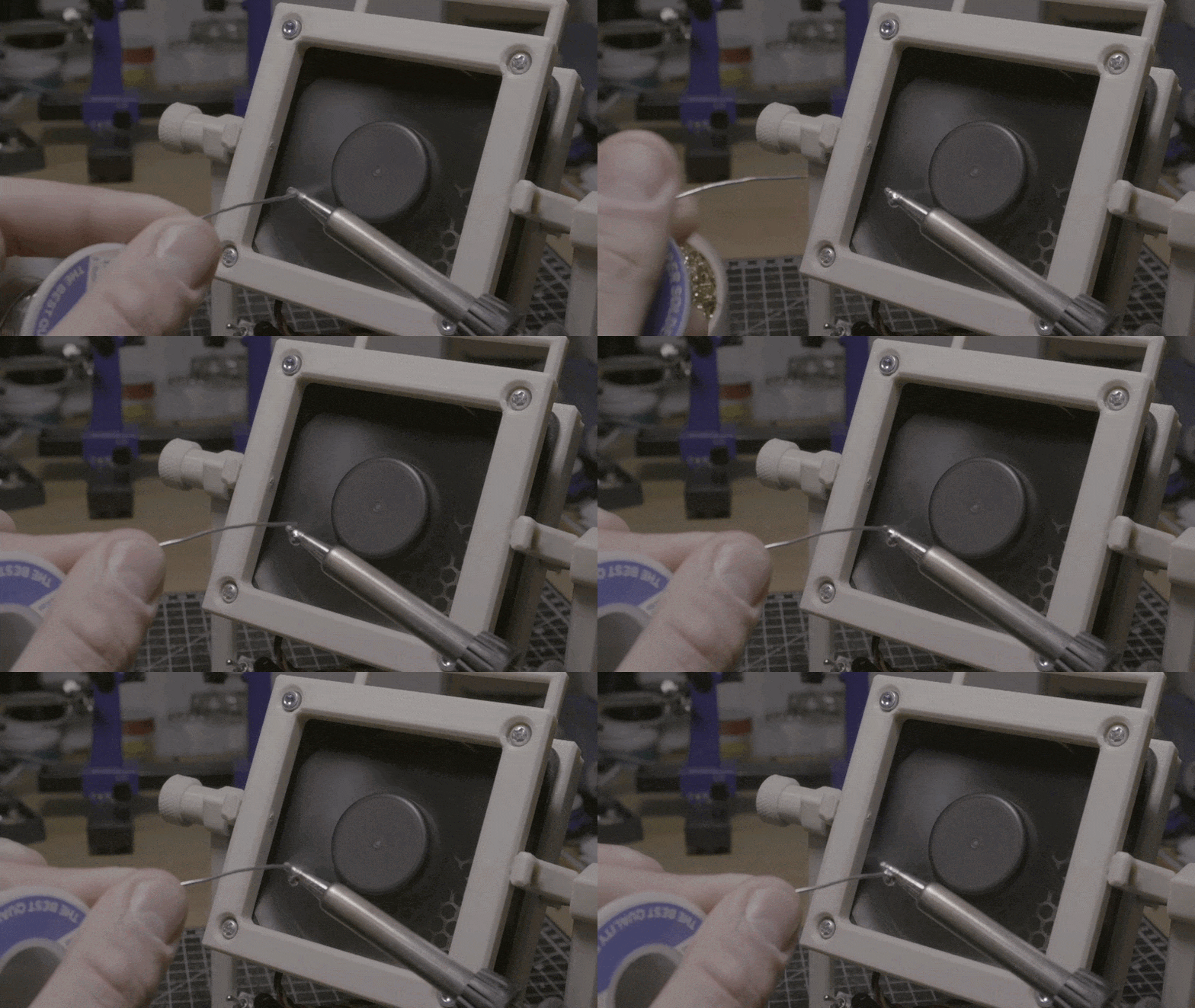
I often find myself using a soldering iron to work on my projects, and this represents a daily exposure to the risk of developing respiratory diseases.
Even using lead-free solder is not completely safe, for this reason, I embarked on a little side project with the hope of actually building something useful while learning more about 3D modeling at the same time.
DESIGN PHASE
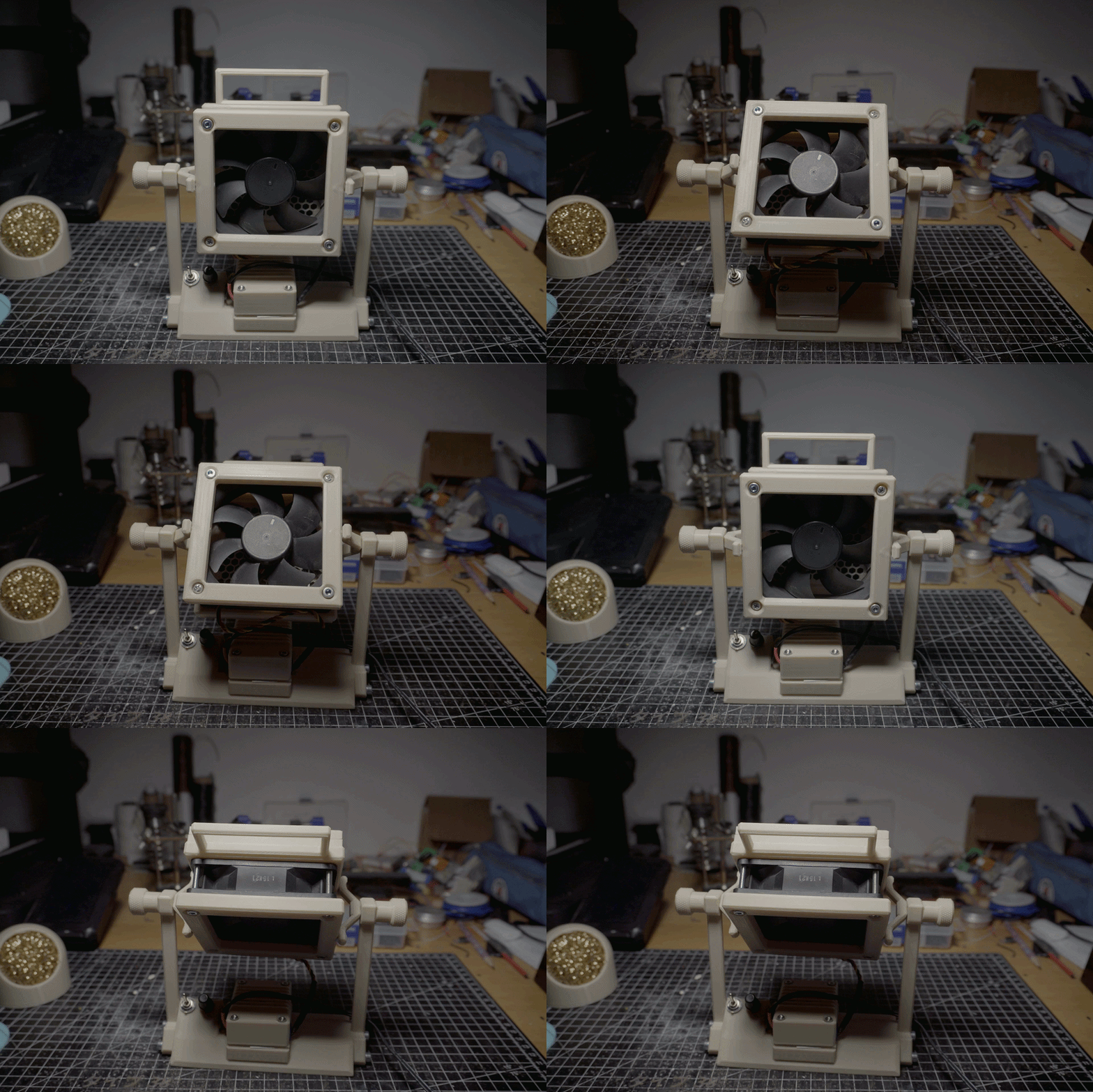
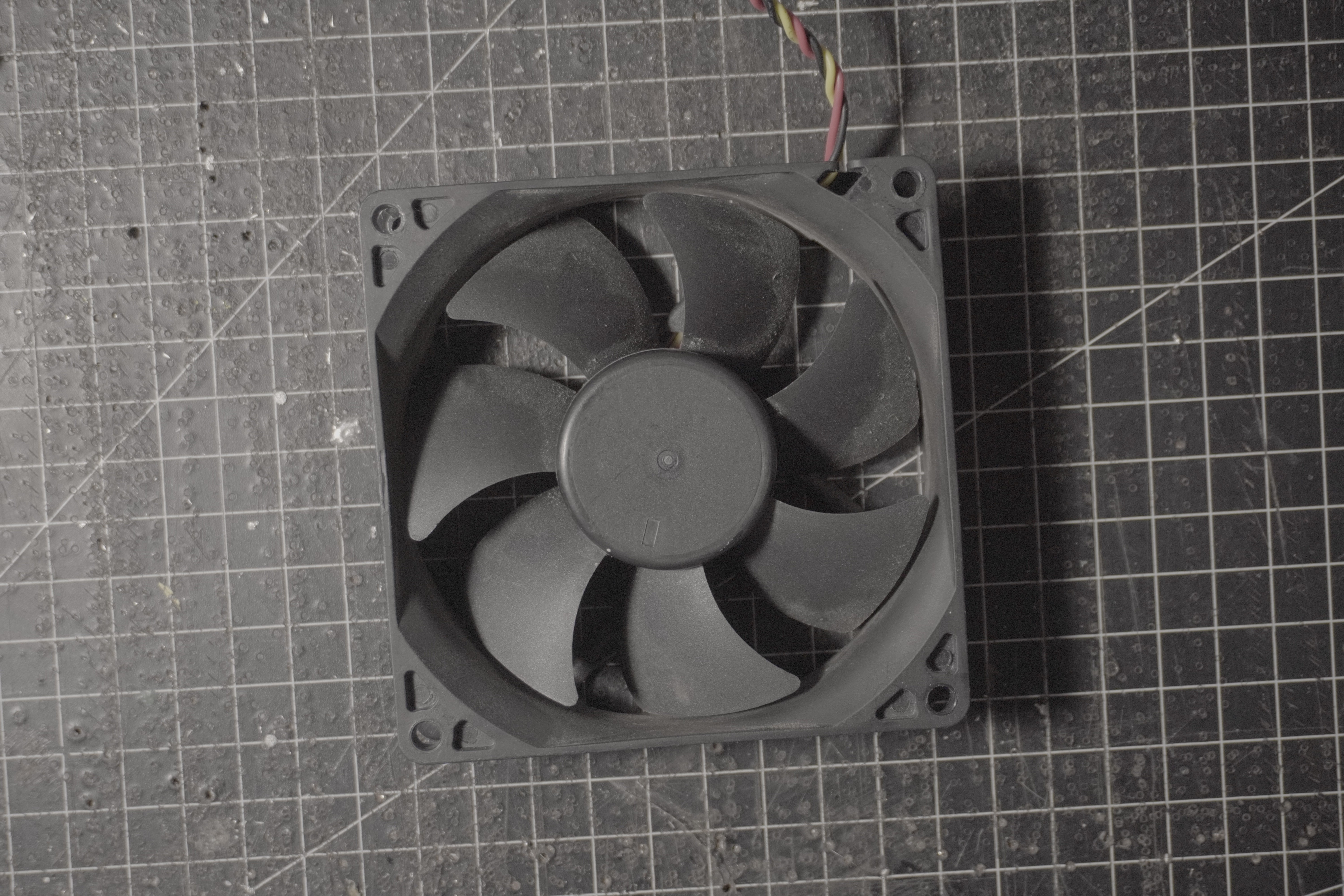
I started to design the extractor unit around an old PC fan that I had lying around in my lab, taking measurements, and then I started sketching a couple of prototypes, trying out different shapes and styles.
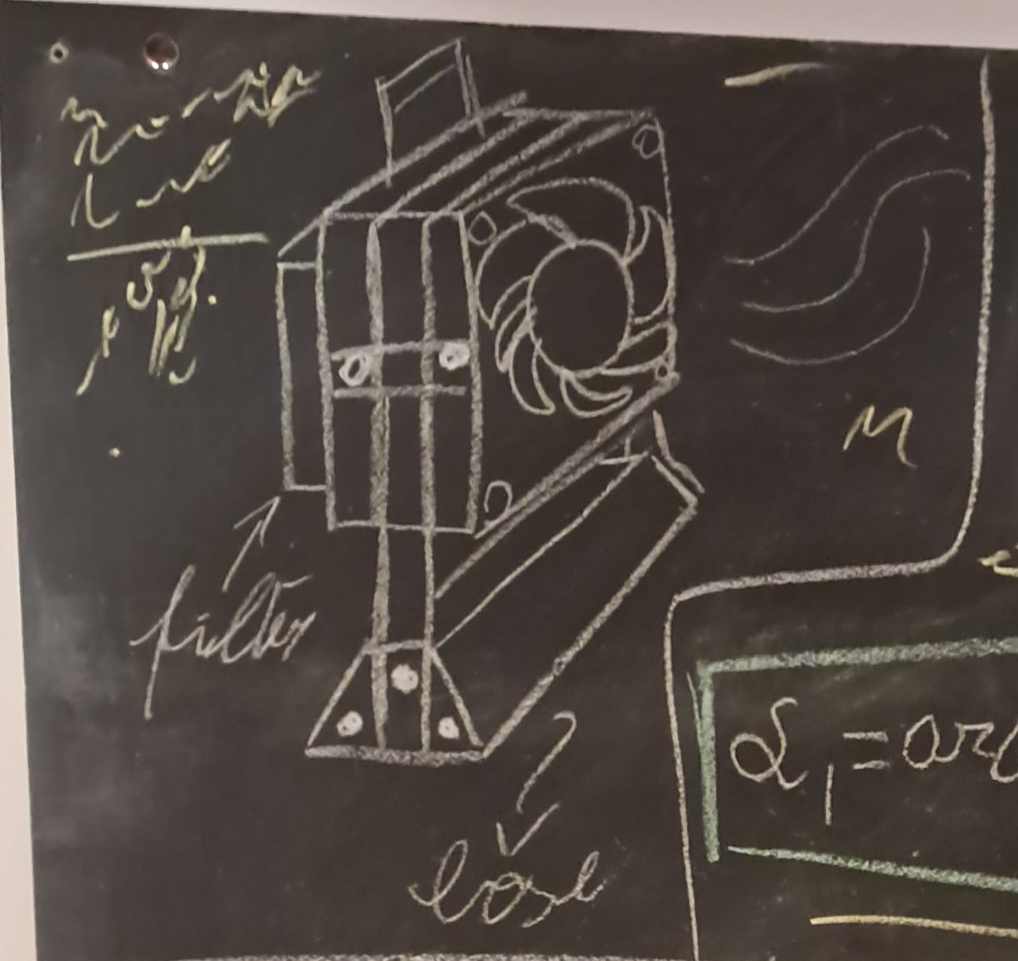
It had to be rugged and practical but also relatively compact and appealing to the eye.
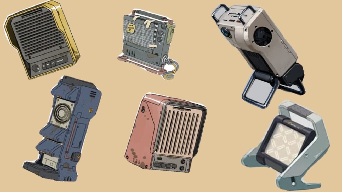
I have always been fascinated by retro futuristic design and its relationship with practical geometry that makes every piece look somehow "rightfully" bulky, giving to every detail a real function.
Following these concepts, I started the 3D modelling process with Onshape, gradually learning how all the different tools and functions worked.
In the end I went for an industrial style with military features taking inspiration from artworks that I found online
3D MODELLING
This was my first "serious" project using a 3D printer and involving 3D modeling.
In the past I have designed and printed simple objects with no specific technical requirements such as stencils and a couple of decorative models for gifting.
This time was different, I wanted to design a humble but still hopefully technical tool.
I started working with OnShape mainly because it was free and cloud-based, I quickly became familiar with the main controls and functions, translating all my (wordefully) hand-drawn designs to a virtual 2D sketch that later became an actual 3D model.
Printing plastic for me holds great responsibility.
Every print has its own cost, both in terms of energy consumption and plastic waste, for this reason, I tried to test every part in software before using PLA filament, carefully ensuring clearances and assembly process to avoid any unnecessary print.
I'm constantly looking for more "eco friendly" materials (In particular for compostable ones) but finding myself out of better options for now I have to stick to PLA+, that according to the manifacturer is produced by corn starch. and other organic sources.
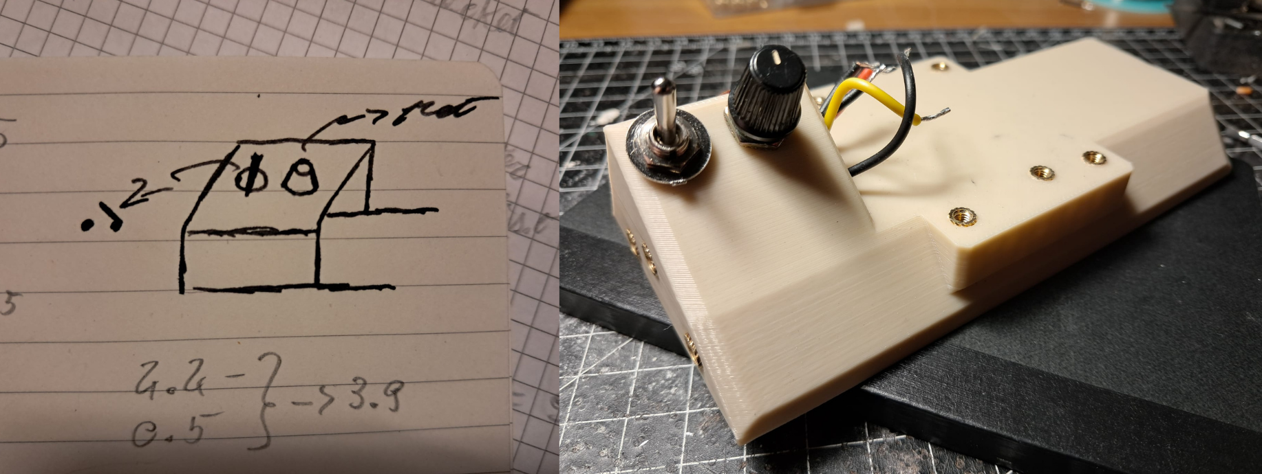
For the base I wanted a low profile shape that would ensure good stability too.
I went for a trapezoid with a modified upper surface to make enough space for the circuit case and the control panel designed to follow the base contour as naturally as possible.
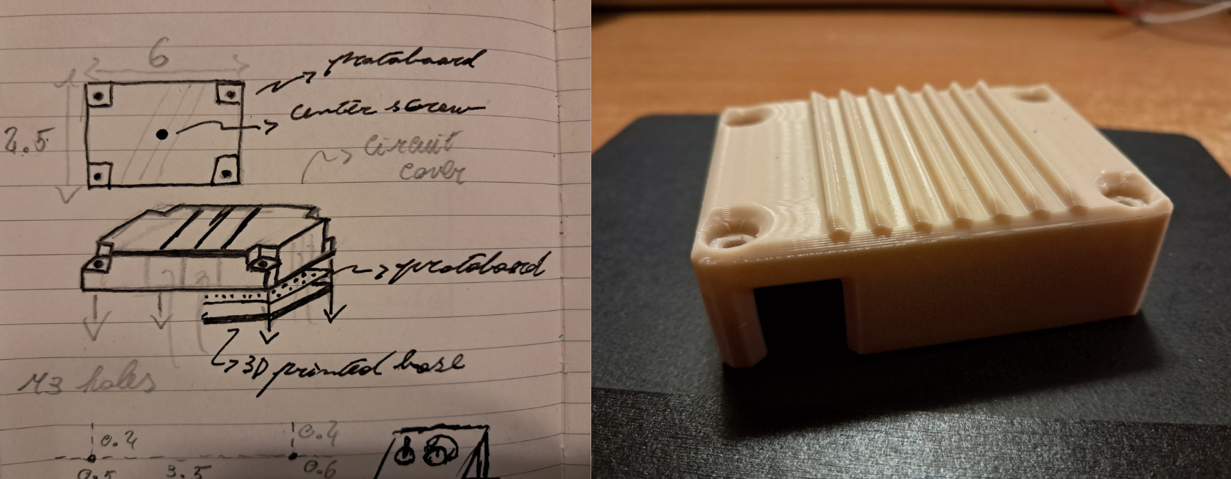
The circuit case was specifically designed for the circuit I made on the protoboard.
There are two holes on the sides, they both leave plenty of room for the power and control connectors.
The internal hollow sections allow housing for all the components.
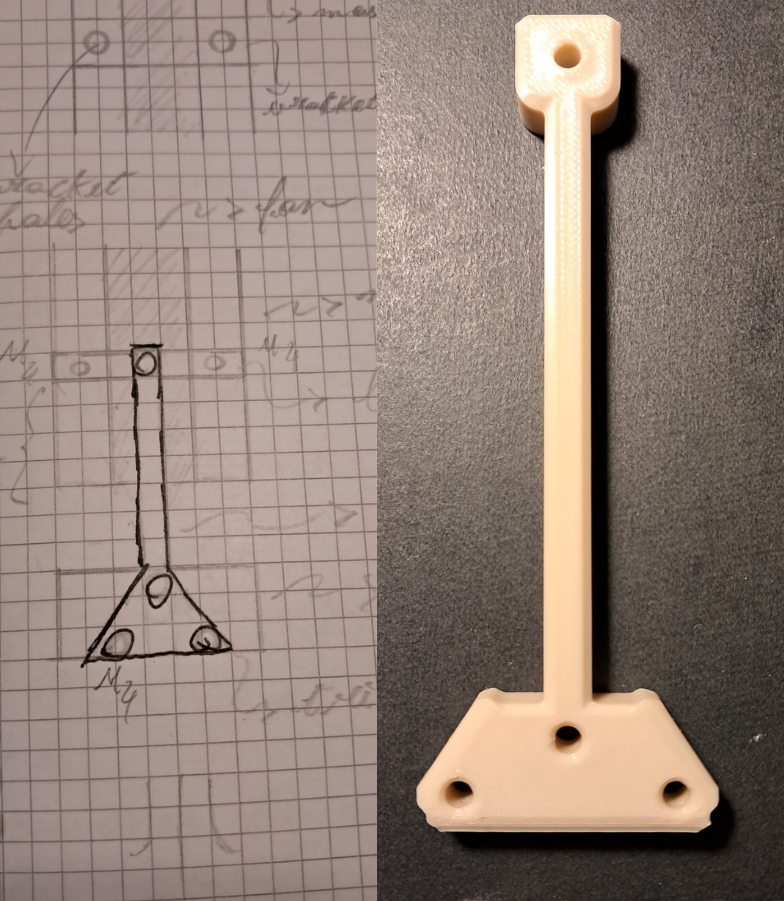
I had to go through a couple of iterations to get the leg model right.
They kept detaching from the printer plate while printing, I later solved the problem by making the end tip wider. I'm also pretty sure this helps the adjusting bolts on the side to get more grip for safer fastening.
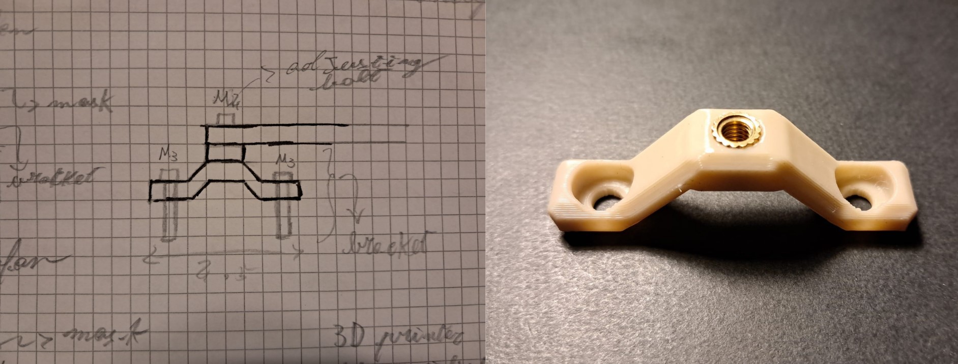
This was one of the most satisfying prints of the project because it came out just as I first imagined it.
It is a pivotal part connecting the base to the ventilation and filtering system.
If I had to redesign it, I would make the bolt holes chamfer less deep, leaving more material just to improve structural stability.
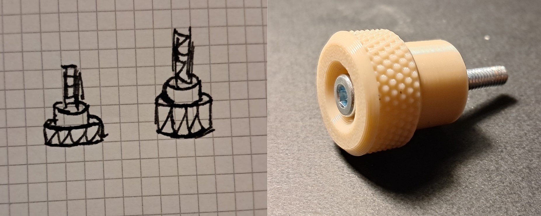
Before this print, I did not believe that a commercial 3D printer could make such precise works as the diamond knurl on the side of this bolt, it made me feel like I was working with a lathe instead of an Ender 3.
CIRCUIT
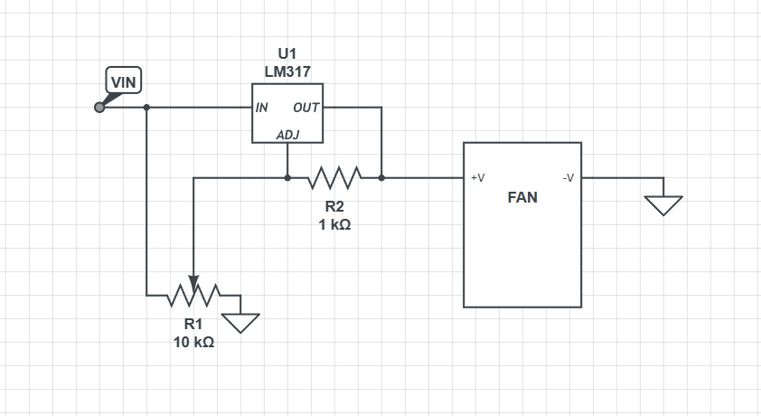
The control circuit is fairly simple, the main component is the LM317 an adjustable voltage regulator extremely common given its versatility.
It is commonly used in combination with two resistors with fixed values to adjust the output voltage in a fixed voltage regulator configuration.
To have a smooth control over the voltage regualtor we are going to swap R2 with a potentiometer (P) with a resistance value that goes from 0 ohm to 10K.
This is the basic circuit you'll need to make the extractor work:
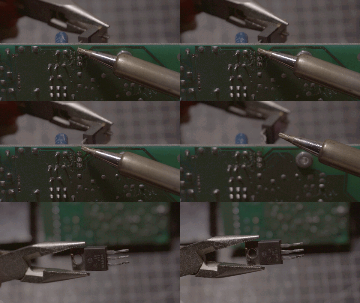
I've added a couple of decoupling capacitors and a reverse polarity protection diode near the input voltage connectors, I was able to recycle all the componets from an old board.
To power up the circuit i'm using an old appliance charger.
ASSEMBLY
I started assembling from the bottom using M4 screws for the structure and M3 screws for the circuit board, you'll probably need to adapt the circuit cover to your board.

The whole assembly process takes a couple of minutes and it is really self-explanatory, the most difficult part is fitting the potentiometer and the switch on the controll panel (due to the lack of space).
FILTERING SYSTEM
I also needed an actual filter, otherwise, I would have built just a fan to move the air around the room while what I was actually aiming for was a way to control dangerous particles coming from the soldering fumes.
For this reason, I also designed an accessible filter compartment for easy maintenance, I went for active carbon filters, they are commonly found and used in stoves and heaters.

For the filter container layer I used an hexagonal pattern structure to avoid the obstruction of airflow while mantaining significant structural integrity.
The filter container has also an handle to carry the extractor around making it more portable.
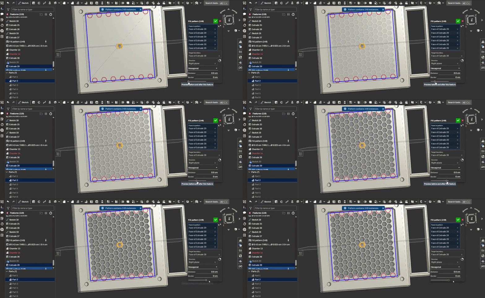
The filter container is wide enough to store several layers of carbon active filter, depending on how much you use your soldering iron you'll need to swap it periodically to ensure decent efficency.
The fume extractor alone is not enough to protect you from soldering fumes, so you should allways use solder in a well ventilated area.
CONCLUSIONS AND THOUGHTS
This project was mainly an excuse to learn how to model using cad-type software, looking back there are several things that I would change but currently I don't have much time to spare.
Surely there's plenty of room for improvements, for this reason I'm sharing not only the files for 3d printing but also the stl file if anyone would like to add modifications or changes to the current design.
I'm leaving here a list of weak points for eventual redesign suggestions:
- Thicker internal honeycomb structure
- Extra screw holes for the circuit board
- Extra space for potentiometer and switch
- Better wire management
- Easier board access