 Olda
Olda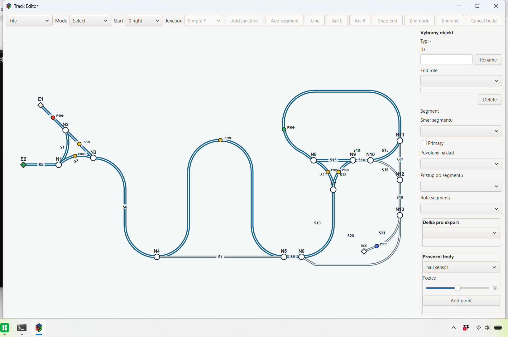
When I started this project, I had to figure out and test many things on my own. Model railway forums contain a lot of information, but they are not always very open, organized, or helpful when it comes to specific solutions. In the end, you search wherever you can, test things, print parts, rebuild them, and slowly put together your own system from many small pieces of experience.
Over time, this project has grown into something much larger than a single hidden magnetic road. A custom Track Editor, Control Monitor, and a set of tools are being developed to automate a large part of both the design and physical construction of the track.
The goal is to keep the physical track, the control logic, and the traffic visualization connected. I do not want one version of the layout on the table, another one in the software, and a third one somewhere in my notes. The whole system is based on the idea that the layout is designed once, and from that single source both the physical parts and the data files for control and simulation are generated.
Track Editor
The Track Editor is a custom program for designing the track. It is not just a drawing tool, but a generator for both the physical and logical form of the system.
The editor works with track pieces from which the final route is assembled. Each segment can contain geometry, direction rules, traffic rules, allowed load state, and connections to other parts of the track. The track is therefore both a physical object and a graph for the control software.
Unlike normal layout drawing, it is not enough to simply connect lines. In this system, every part also has a mechanical meaning. A vehicle cannot magically turn around in place, a long vehicle may not be able to pass through every junction, and some sections may only be allowed for empty or loaded vehicles.
For that reason, the editor does not only describe the visual shape of the route, but also the rules that will later be used by the control applications.
STL generation
STL generation already works in the editor. The program can create physical 3D-printable parts from the designed route.
This is one of the most important parts of the whole project. The track is not created by manually drawing every part separately, but as an output from the editor. The same design is therefore used both for printing and for traffic control.
The editor can work with physical segments, split them into printable parts, and prepare STL files. This makes it possible to design a route, generate the parts, print them, and use the same data in the Control Monitor.
This approach greatly reduces manual work and, more importantly, reduces the risk that the physical and software versions of the track will start to drift apart.
Vehicle and accessory configurators
The same principle can also be used for vehicles and other layout elements.
The goal is for the program to generate not only the track, but also configurable vehicle models and accessories. For example, a truck can have different chassis variants, axle counts, body types, or working roles.
In the same way, the system can later generate other trackside elements: embankments, holders, signals, turnout parts, service points, or other layout components.
Over time, this creates a library of elements that are not just one-off hand-made models, but parts of a larger system.
Control Monitor
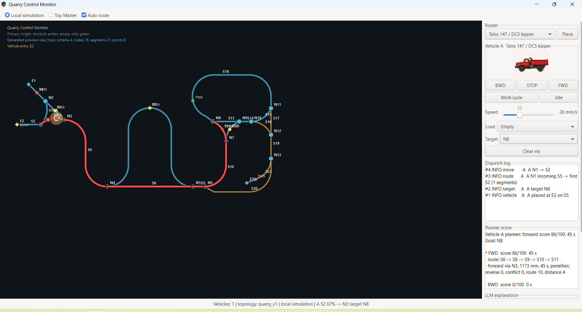
The Control Monitor is the second part of the system. It is a separate C/GTK application that loads the data generated by the editor and uses it for simulation, visualization, and debugging of traffic.
The editor creates the track.
The Control Monitor operates it.
The monitor can display the track topology, vehicles, planned routes, occupied and reserved segments, the dispatch log, planner score, and other information. It can simulate vehicle movement without real hardware and verify whether the route logic matches what was designed in the editor.
The screenshots show the Control Monitor with a quarry route, a Tatra 147 / DC5 tipper, route planning, and the debug panel.

System automation
The whole project is moving toward automating as much of the track creation and operation as possible.
In the past, many things had to be solved manually: track geometry, physical parts, connections, rules, exports for the control software, and later also the traffic logic. Now these parts are gradually being connected into a single workflow.
Ideally, the route is designed in the editor, the STL parts are generated, printed, the data export is loaded into the Control Monitor, and the electronics are connected.
On the hardware side, I try to keep the approach as simple as possible. To get the basic peripherals working, it is enough to understand the wire colors on a servo and correctly connect plus, GND, and signal to the ESP. The control software can then take care of the rest.
LLM layer
The Control Monitor also includes a local LLM layer. This is already working and can turn debug data into a human-readable explanation of what is happening in the system.
The monitor prepares context from the current state, planner output, and dispatch log. A local language model then creates a short explanation. This is not an online service; the model runs locally through llama.cpp.
For example, a technical state such as a segment blockage or a planner result can be converted into normal text. The program then feels less like a table of states and more like a dispatch system that can describe what is going on.
It is a small detail, but it changes the feel of the whole application quite significantly. Even a simple sentence from the LLM layer makes the Control Monitor feel more like a living operating system than just a debugging window.
Project direction
The Track Editor and Control Monitor are gradually becoming the center of the whole system. This is no longer only about a magnetic carriage hidden under a road, but about a broader tool for creating model traffic systems.
The same principle can be used for road transport, a quarry, conventional railway track, embankments, signals, vehicles, accessories, and other layout parts.
The project is naturally moving toward something like a small “layout factory”: a tool that connects design, physical manufacturing, traffic control, simulation, and debugging.
Possible release of a demo version
At the moment, I am not publishing the project as a complete build kit or as finished software. The production files, internal part libraries, and the full version of the editor are still closely tied to my own development, mechanics, and test layout.
However, if there is interest in this part of the project, I am considering releasing a limited demo version of the program. It could demonstrate the basic workflow: designing a simple route, exporting data, generating sample STL parts, and loading the result into the Control Monitor. It could also include the LLM layer integration and the basic configurators for vehicles and track accessories.
Discussions
Become a Hackaday.io Member
Create an account to leave a comment. Already have an account? Log In.