 tokaken
Game
The outline of the game is as follows.
When there is a phone request, the LEDs of two ports light up in the same color. These represent the caller and the receiver.
When you connect the ports of the same color using a USB cable, the connection is successful. This means you have successfully processed the request.
The objective is to process as many phone requests as possible within the time limit.
-> The more requests you process, the higher your score becomes.
Requests disappear after a while.
You can use any number of USB cables at the same time.
Game Screen
The game screen displays instructions on how to play and a panel corresponding to the controller. I worked hard to create it, but since most players play by looking at the LEDs on the controller, the game screen might not actually have been necessary.
Controller
The controller consists of 24 USB ports, 24 LEDs (each USB port and LED are arranged as a pair), and one button.
The USB connectors are Type-A. Therefore, when connecting connectors to each other, USB cables with Type-A connectors on both ends are required, but these are not normally available. USB has standards, and connections are based on a host-device relationship. Type-A is normally used on the host side, so if one end is Type-A, the other end is usually the device side, such as Type-B or micro Type-B. It is not normal for both ends to be Type-A. However, such cables can be found easily on sites such as AliExpress. Another reason I chose Type-A connectors is that they have a specific orientation; the frustration of trying to plug one in and failing because it is upside down also contributes to the difficulty. The button is used for actions such as starting the game.
Why Can the Controller Detect Connections?
This controller detects when connectors are connected to each other. At first glance, this seems easy to implement. But is it really? How do you think this controller is implemented? Imagining and predicting how something works is very important in making things.The requirements this controller needs to satisfy are listed below.
- It can tell that a connector is not connected to another connector.
- It can tell that a connector is connected to another connector.
- If a connector is connected, it can identify the number of the connector it is connected to.
Unless these three requirements are satisfied, this controller cannot be implemented.
If we think about it simply, when a cable is connected, two points become electrically connected, so it may seem possible to implement this function by detecting that. However, doing so would require a huge matrix switch, probably. This is not very realistic. Complex wiring makes creation and modification difficult, which increases the difficulty of the project. In the first place, I feel like there would not be enough microcontroller I/O pins.
So, What Do I Do?
We loosen the previous requirements a little.- It is enough to be able to detect whether two specified ports are connected.
It is not necessary to detect connections between those two ports and any other ports. - These two ports can be changed dynamically.
To implement this, I used an FPGA. The reasons are as follows.
- The direction of the I/O can be changed dynamically.
- There is a reasonable number of I/O pins.
A USB port consists of four wires, and one of them is used as a communication line. The communication line has either an INPUT or OUTPUT direction, and this direction can be switched dynamically.
- In OUTPUT mode, the port continuously sends its own port number via serial communication.
- In INPUT mode, the port waits to receive data via serial communication.
At this time, when an INPUT port and an OUTPUT port are connected by a cable, the INPUT port can recognize the data from the connected OUTPUT port. Since the OUTPUT port is sending its own port number, the connected port can be identified. This mechanism only works when an INPUT port and an OUTPUT port are connected. The relationships are shown below.
| Port A | Port B | When Connected |
| INPUT | INPUT | Nothing happens |
| INPUT | OUTPUT | A obtains B’s port number |
| OUTPUT | INPUT | B obtains A’s port number |
| OUTPUT | OUTPUT | Nothing happens |
Controller Circuit
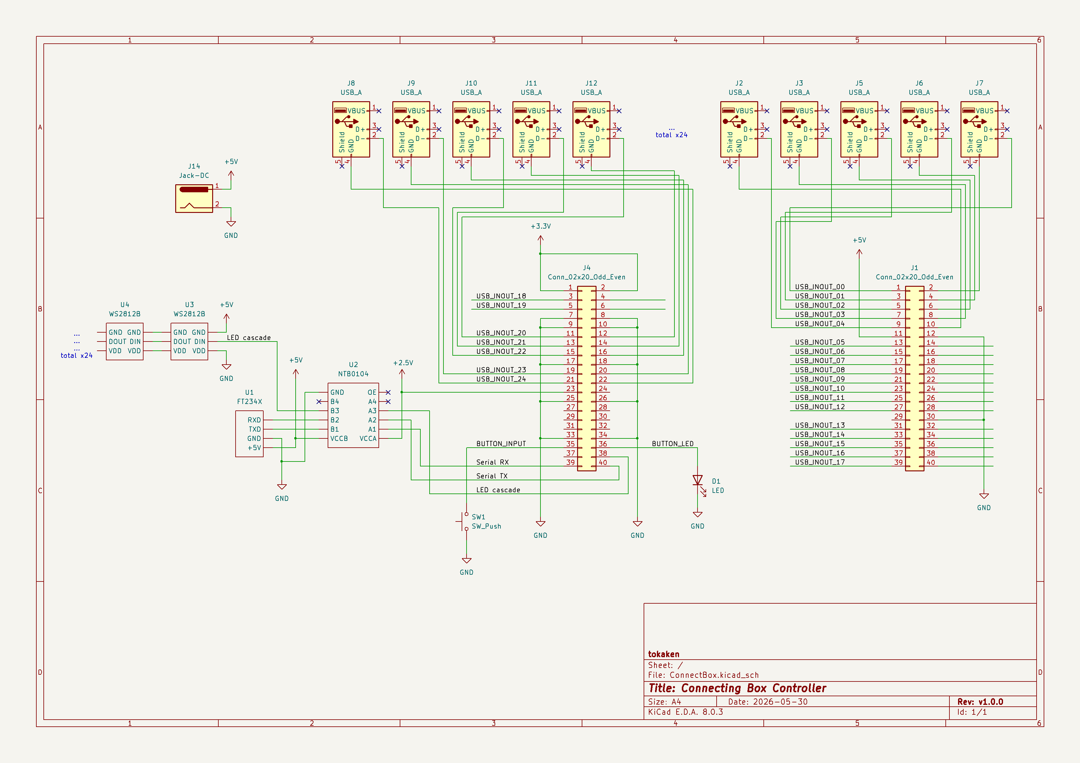
Commands
The controller sends the current status of all ports to the PC at once. Serial communication is used for this.
Commands from the PC can also set each port to INPUT or OUTPUT and set the LED color.
Summary: Game Control Flow
- Each of the 24 ports has serial communication transmit and receive functions.
- Each port’s serial communication transmit(OUTPUT) and receive(INPUT) modes can be switched dynamically.
- From the game side(PC), a pair of ports is randomly selected as a phone request. One is set to INPUT and the other to OUTPUT, and their LED colors are set.
- If those ports are connected by a USB cable, the INPUT receives the serial communication from the connected OUTPUT, and that information is sent to the game side(PC).
- On the game side, the PC recognizes that the ports have been connected and performs score calculation and other processing.
- Return to step 3. until the time limit ends.
LED
The LEDs are WS2812B, controlled by connecting 24 of them in a cascade. I used masking tape for the LED windows. This helped diffuse the LEDs very well. The following eight color patterns are used.- Red
- Blue
- Green
- Cyan (light blue)
- Magenta (purple)
- Yellow
- White
- Off
Other Notes
What I learned from exhibiting it is that the cable quality is poor
Using a different cable allows for connection confirmation, so there may be a contact problem or a broken wire. I brought 10 USB cables to the exhibition, but ultimately half of them were broken. The cable may be of low quality because it does not conform to the USB standard.Since USB has a complex structure, it might be better to use a simpler earphone jack instead. High-quality earphone jack cables are readily available, and contact problems could be avoided.
Someone was connecting a blue port to a purple port
Do you know why he did that?
When I pointed out his mistake, he replied, "I’m colorblind." In other words, he couldn't distinguish between blue and purple. I am not colorblind myself, but I was aware of the condition. I realized then that such factors must be taken into account to ensure a game can be enjoyed by everyone.
Using only one cable results in a higher score than using multiple cables
I originally intended for multiple cables to be used, but it didn't work as expected. This is because a request is generated, and the request disappears the moment the cable is connected, making it possible to disconnect the cable. If the motif is a telephone operator, the connection should remain open for a while after connecting the call (conversation usually takes place on the phone), which would create a reason to use multiple cables. This is a feature that couldn't be implemented due to lack of time. I think using multiple cables would increase the difficulty, make it more confusing, and therefore more interesting.