 Marco Tabini
Dr. PD is crowdfunding soon! Sign up at our prelaunch page on Crowd Supply to receive product updates.
In the last decade or so, USB-C has become the dominant standard for power and data transmission. Despite the occasional attempt at proprietary formats (Lightning, anyone?), practically every device these days comes with the ubiquitous rounded port.
Without a doubt, this success is well deserved: USB-C cables are easy to acquire and inexpensive, compatible power supplies can be had for less than the cost of an espresso beverage, and inserting a plug into a receptacle does not require a degree in quantum physics.
These capabilities, however, come at a cost. USB-C receptacles and cables are surprisingly complex, and designing hardware around them can be challenging even if you decide to use off-the-shelf parts.
Anatomy of a USB-C port
Let's start by looking at a “full” USB-C port and its signals:
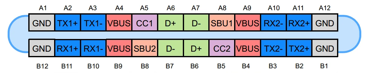
Let's go through these in detail:
- GND and VBUS carry power to and from a device. By default, only 5V is available, with analog signaling on CC1 and CC2 used to advertise or detect up to 3A of current. By using Power Delivery, however, devices can negotiate various voltage and current combinations up to 48V and 5A—a whopping 240W of power.
- CC1 and CC2 can be used for four (!) purposes:
- By manipulating the analog characteristics of these lines, a device can advertise 5V at either 500mA, 1.5A, or 3A without the need for more advanced digital negotiation. Default USB current corresponds to the legacy USB current level, typically 500 mA for USB 2.0 or 900 mA for USB 3.x.
- One of the two lines can be used to provide VCONN, a special 5V power rail capable of providing up to 1W of power that can be used to power accessories independently of VBUS. This is useful because an accessory may need 5V to function, but then request a higher (or lower) voltage to be delivered on VBUS to power some of its peripherals or another device. Notably, VCONN does not normally pass through the cable end-to-end; it is used to power circuitry in the cable or plug assembly and is typically not presented as a usable rail at the far end.
- The other line can be used for Power Delivery signaling. By using a dedicated serial protocol, devices can exchange information, negotiate a power contract to deliver a voltage different from the standard 5V alongside specific power and current capabilities, or enter Alternate Modes that repurpose some of the data lines in the cable for something other than ordinary USB communication. For example, monitors use an Alternate Modes to receive video data from a host device.
- Because each line takes on a different role, their relative position is used to determine the orientation of the cable in the receptacle.
- The SBU pins are used for “sideband” data. They provide an independent low-speed (up to 1MHz) channel that can be used for custom out-of-band communication between compatible devices. For example, DisplayMode Alternate Mode uses them for AUX signaling, and USB4 can also use them for sideband functions during link management and initialization.
- D+ and D- are traditional USB 2.0 data lines. These represent a single differential pair and run as a twisted pair inside the physical cable, and are capable of serial speeds up to 480Mbps.
- TX+, TX-, RX+, and RX- are SuperSpeed differential pairs. In a full-featured USB-C connection, these high-speed pairs can be used for protocols such as USB 3.x, USB4, Thunderbolt, or Alternate Modes. In the newest USB4 mode, the total link rate can reach 80 Gb/s symmetrically or 120 Gb/s in one direction with reduced bandwidth in the other. As I mentioned above, these lines can also be repurposed to carry non-USB data through Alternate Modes.
If this seems complicated… well, it is. A good, if somewhat reductionist, way of looking at how all these lines relate to each other is:
- D+ and D− are legacy USB 2.0 data lines. They are there to support devices that use the physical USB-C connector but are not necessarily interested in the more advanced communication features associated with USB 3.x or USB4.
- The CC lines are used to detect attachment and cable orientation, advertise or detect default USB-C current, carry USB Power Delivery signaling, and, on the unused CC conductor, potentially provide VCONN. They therefore play the central role in determining how the two devices on the cable will use the remaining lines.
- The TX and RX lines are used for high speed communication; the kind of data they carry depends on the mode in which the two devices set up their link. In a conventional USB3 or USB4 connection, they are used as SuperSpeed lanes; in an Alternate Mode, they can be repurposed to carry other kinds of information, such as video data.
- SBU1 and SBU2 are used for dedicated for signaling specific to the type of link that the two devices establish with each other. They are separate from the TX/RX lines because they are meant for low-speed auxiliary signaling without disturbing the main high-speed data path. They are also separate from CC1/CC2 so that they can carry arbitrary data without having to either implement or interfere with the USB-PD communication that happens on the CC lines.
What is a USB-C port, though?
Despite the fact that I just spent a considerable amount of words telling you about the many pins that make up a USB-C cable, it might surprise you to learn that there isn't just “one” kind of USB-C port. In fact, a device may use one of several connector variants, depending on what subset of functionality it requires.
Typically, hardware manufacturers market plugs and receptacles based on the number of populated contacts (or positions) they provide. If all you care about is a basic 5V power supply, you can buy so-called 2P receptacle that only contains a pin connected to VBUS and one connected GND:
If, on the other hand, you want to take advantage of Power Deliver to negotiate higher voltages and currents, you could upgrade to an 8P plug, which gives you access to the CC lines and USB2 data:
And so on, all the way up to the 24P ports, which support every line.
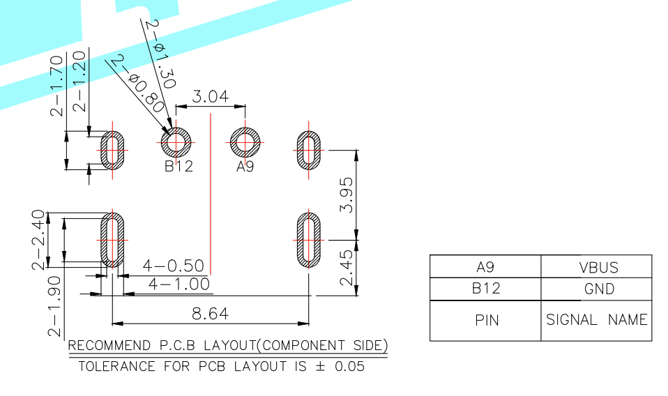
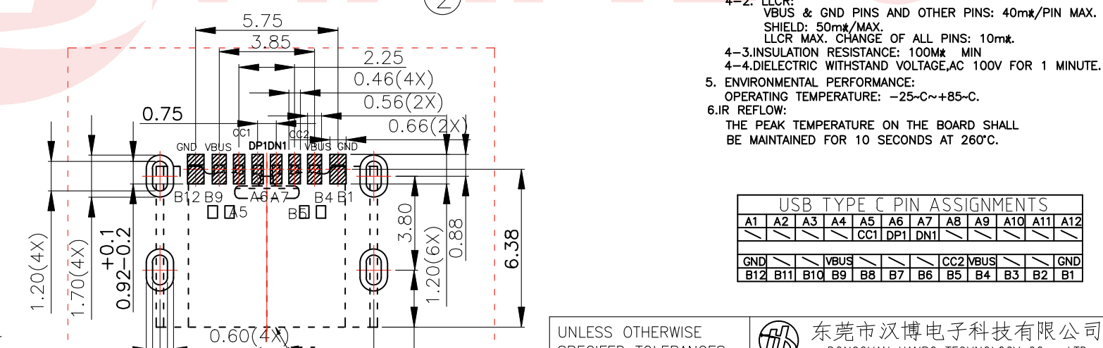
A notable oddity is a particular kind of 12p port that provides VBUS, CC, D+/-, and, inexplicably, the SBU lines:
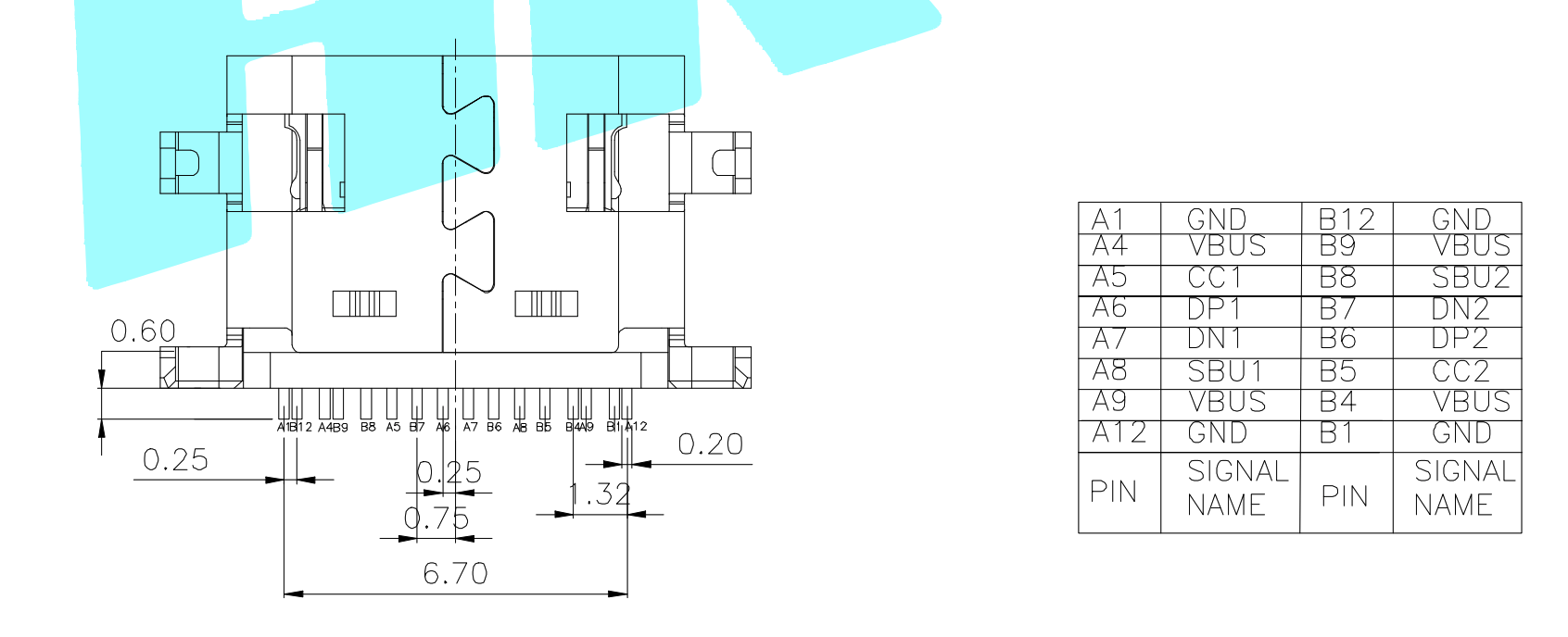
At first sight, this makes little sense, since SBU1 and SBU2 are typically only used in modes that also involve additional USB3/4 functionality that requires at least some of the TX and RX high-speed lanes. It turns out, however, that there is a special “audio adapter” mode that uses (though I think the more appropriate term here would be “misuses”) several of the digital lines to transmit analog audio. In that mode, D+ and D− can carry right and left audio, while SBU1 and SBU2 can be used for microphone and analog ground functions.
This complexity is not limited to plugs and receptacles; cables—which we'll examine in detail in a future project update—are even more confusing: They can be power only, USB2 and power, or USB3/4 with one or two TX/RX pairs… plus, they can also act as active repeaters for longer run or noisy environments, and even require active circuitry in order to support higher voltages and currents.
But wait, it gets worse
Particularly compared with their predecessors, USB-C ports are a great step forward in terms of usability for the simple reason that they are reversible: it doesn't matter which way you attempt to plug them in—they will always work.
This is great news for anyone who has ever attempted to blindly insert a USB-A or micro-USB cable into the back of their computer, but the folks who designed the USB-C electrical layout elected not to extend the same courtesy to engineers who want to incorporate a USB-C port into their designs.
Let's look at the port layout from the beginning of this post again, only this time placed top-to-bottom with a copy that has been rotated by 180 degrees to simulate what happens when the user chooses either orientation:
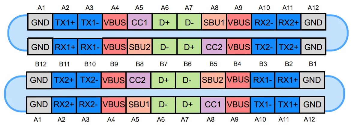
As you can see, from an electrical point of view there is very little reversibility here.
GND, VBUS, and the USB 2.0 lines occupy effectively the same positions in both orientations. This makes sense because handling reversibility on the power rails would be difficult, especially at higher voltages and currents, and the USB 2.0 connection must remain compatible with an older standard that has no concept of reversibility at all. USB-C handles this by duplicating the relevant receptacle contacts so that both plug orientations connect to the same USB 2.0 pair and power rails.
Meanwhile, the TX/RX and SBU lines are effectively reversed, which means that the host or port controller must somehow determine the plug orientation so that it can route the appropriate signals to the correct pins. This is accomplished using the CC lines: the system detects which of CC1 or CC2 is actually connected, and from that determines plug orientation and configures the SuperSpeed signal routing accordingly (don't worry if this sounds confusing, there will be a post about this, too!).
Why is USB-C so successful then?
If this seems overly complicated—well, it is. USB-C bears all the hallmarks of a designed-by-committee standard that somehow had to find a compromise among the needs of a disparate group of stakeholders. If you look at the list of people who contribute to the various standards that make up USB3 and USB4 and their employers, you will find a veritable who's who of the tech industry: Apple, Dell, Samsung, Microsoft, Texas Instruments, and many, many more. It's no surprise that they ended up with a standard that mixes analog and digital signals, repurposes lines, and requires a nontrivial amount of work to figure out which lines to use and how.
Still, USB-C is enormously successful because it is designed with the convenience of the end user in mind. It's much easier to use and more capable than earlier USB connectors, and has been adopted so widely that the cost of ownership is rapidly converging on the material cost of cables and power supplies. It's a winner in almost every sense (one notable exception being cables, which, as we'll see in a later post, are not as user-friendly as they should be), and that's why users have enthusiastically adopted.
On the implementer side, the complexity is usually mitigated by the use of specialized chips that handle orientation detection and power negotiation, exposing straightforward configuration interfaces that are easy to implement in just about any hardware product.
Sure, these chips cost money, but they are widely available and relatively inexpensive. In return, designers get access to extremely capable power supplies at a fraction of the cost of anything custom you would otherwise have to acquire separately, and can almost always count on the user having access to several compatible cables and power supplies, reducing waste and support costs.
The major downside is that the entire USB-C physical and power stack becomes completely opaque; if anything goes wrong—or even if you just want to characterize your power supply to make sure that it meets your needs—your choices are either manual probing with an oscilloscope, or relying expensive closed-source tools.
Of course, that's where Dr. PD comes into play! If you want your own, you can join our prelaunch page on Crowd Supply for product updates, or stay tuned here for more posts on USB-C, Power Delivery, and the hardware design behind Dr. PD.
Discussions
Become a Hackaday.io Member
Create an account to leave a comment. Already have an account? Log In.