 Marco Tabini
In my previous project update, I mentioned that the CC lines in a USB-C connection are used to determine the orientation of the plug within the receptacle. Let’s explore how that works and why it poses a particular challenge for a device like Dr. PD, which needs to interpose itself between two USB-C devices.
The double life of the CC lines
Despite the fact that there are two CC pins, only one is used for USB-PD communication between the two ports. The other may be used to supply VCONN, and in a passive cable it typically does not continue through to the far-end CC pin. Instead, VCONN is primarily used to power electronics inside the cable, such as an e-marker, or electronics in certain captive-cable devices such as docks designed to attach to laptops or tablets.
When you plug a cable into a device, then, from the device's perspective, one of the CC lines will be floating, while the other will be able to carry a signal across to the other device.
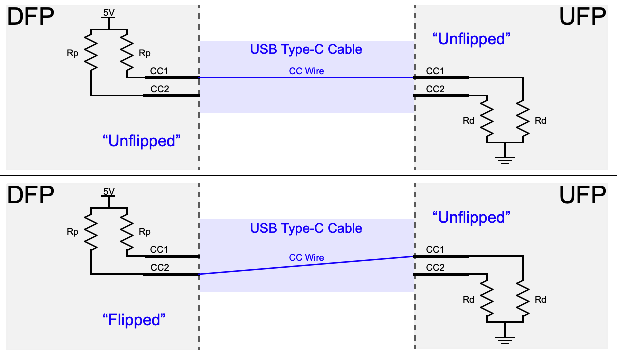
The problem is, which of the two CC lines do you use for transmission? Because the USB-C plug is mechanically—but not electrically—reversible, either CC pin may end up being the active one, depending on how the user inserts the cable. Thus, a device must be prepared to communicate on either pin, and the very first thing it needs to do is to figure out which one is actually connected through.
Analog signaling
The way the USB-PD designers have solved this challenge is to first define what a valid CC connection must look like.
At one end, there is a downstream-facing port, or DFP. The DFP is typically a host or power supply and is responsible for sourcing current on VBUS.
At the other end, there is an upstream-facing port, or UFP, that wants to sink current from a UFP.
(Sometimes, a device can act as both a UFP and a DFP, in which case it is called a dual-role port. For simplicity's sake, we will ignore this for now, but we'll come back to it in a future post.)
When they are connected, the UFP and DFP must form a complete circuit, with the DFP pulling both its CC lines to either 5V or 3.3V (the latter being much more common these days), and the UFP pulling both its CC lines down to ground, as you can see in the diagram below, borrowed from this very informative Microchip application note:
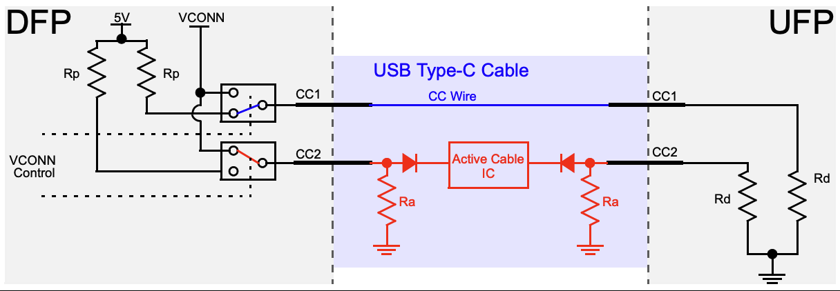
When a connection is successfully established, one of the two CC pins will complete a circuit between the two devices; all the devices need to do is monitor both pins for a valid CC voltage and, when they detect one on either pin, select that pin as the communication channel for USB-PD data. In the diagram above, CC1 is connected at both ends, but either CC pin could end up being the connected one on each device depending on the cable’s orientation.
Well, this complicates things…
Having to deal with two possible cable orientations is a bit of a pain, but most devices never have to worry about this problem because someone else has already solved it for them. Even the most basic USB Type-C or USB-PD port controller can monitor both CC lines and automatically communicate over the one that is connected through to the other side, and more advanced chips may even provide a dedicated pin that changes state depending on which CC line is detected as active and can be fed directly into other controllers that reroute the signals on the high-speed lines accordingly.
Dr. PD, on the other hand, is not a “traditional” USB-C device. In some cases, it must interpose itself between two devices while appearing electrically transparent to both, so that it can “listen” to and decode the USB-PD data being exchanged between them. In other cases, Dr. PD will be the UFP and will have to communicate with a DFP connected to one of its ports.
Traditionally, this kind of interconnectivity can be managed using a crossbar switch that is capable of connecting either of the CC lines on one port to either of the CC lines on the other. Analog crossbar switch ICs are plentiful, inexpensive, and easy to use, but they do present a few challenges for our use case.
First, crossbars perform all their switching internally. While that's sufficient to connect one device to another, Dr. PD also needs to intercept and decode the communication that's happening, and this would require either using two physically separate pins on the microprocessor (four if you want to be able to monitor each port separately), or adding one more multiplexer to reduce that number down to one pin. I/O is always a constrained resource, and so this is generally not a good thing.
Second, one of Dr. PD's defining features is a dedicated “CC” output that can be connected to an oscilloscope to independently monitor activity on the CC line without having to worry about which line is currently carrying the signal. With a normal crossbar switch, this would be difficult to do, again at least without the use of another mux.
Making a “crossbar” switch, the hard way
The way I ultimately ended up solving this problem is to use three 2:1 muxes to do the job of a single crossbar switch, plus a few extra bits:
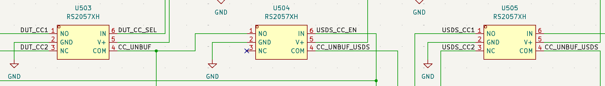
The RS2057XH takes two analog signals on pins 1 and 2, and connects one of them with the common end on pin 4 depending on the state of the IN line on pin 6. Basically, it's a solid-state SPDT switch capable of routing signals up to 5.5V.
U503 connects to the two CC lines on the “DUT” port of Dr. PD, while U505 connects to the same lines of the “US/DS” port. (The names of these ports are somewhat arbitrary, since USB-C is a bidirectional standard.) The common line of both of these chips is connected to U504, which just acts as a simple switch that can be used to disconnect one port from the other. The COM line of U503 is what is then used by the system as the “unified” CC line that is monitored for messaging.
At runtime, the firmware then implements this simple algorithm:
- Disable the connection between the two ports by driving the IN line of U504 so that it is routes to its NC connection.
- Cycle through all four CC lines, looking for one that carries a voltage of at least 3V. When you find one, mark it as a likely DFP candidate.
- Now cycle through the CC lines on the other line and look for one that, when connected to the DFP candidate port, brings the voltage down to below 2V. If you find one, mark this as a UFP candidate and mark the connection as established.
This works remarkably well, although it took quite a bit of effort to determine good debounce times for the various states. In particular, when you connect two dual-role devices, which periodically switch between acting as a UFP and a DFP while trying to establish communication, you have to give each device enough time to settle into the right state for a connection to be established.
So, there you have it: A relatively simple solution to an unexpectedly complex problem—one of many I've encountered while designing Dr. PD.
Discussions
Become a Hackaday.io Member
Create an account to leave a comment. Already have an account? Log In.