 Arnov Sharma
Here's a demo of Conway’s Game of Life running on a full-sized monitor.
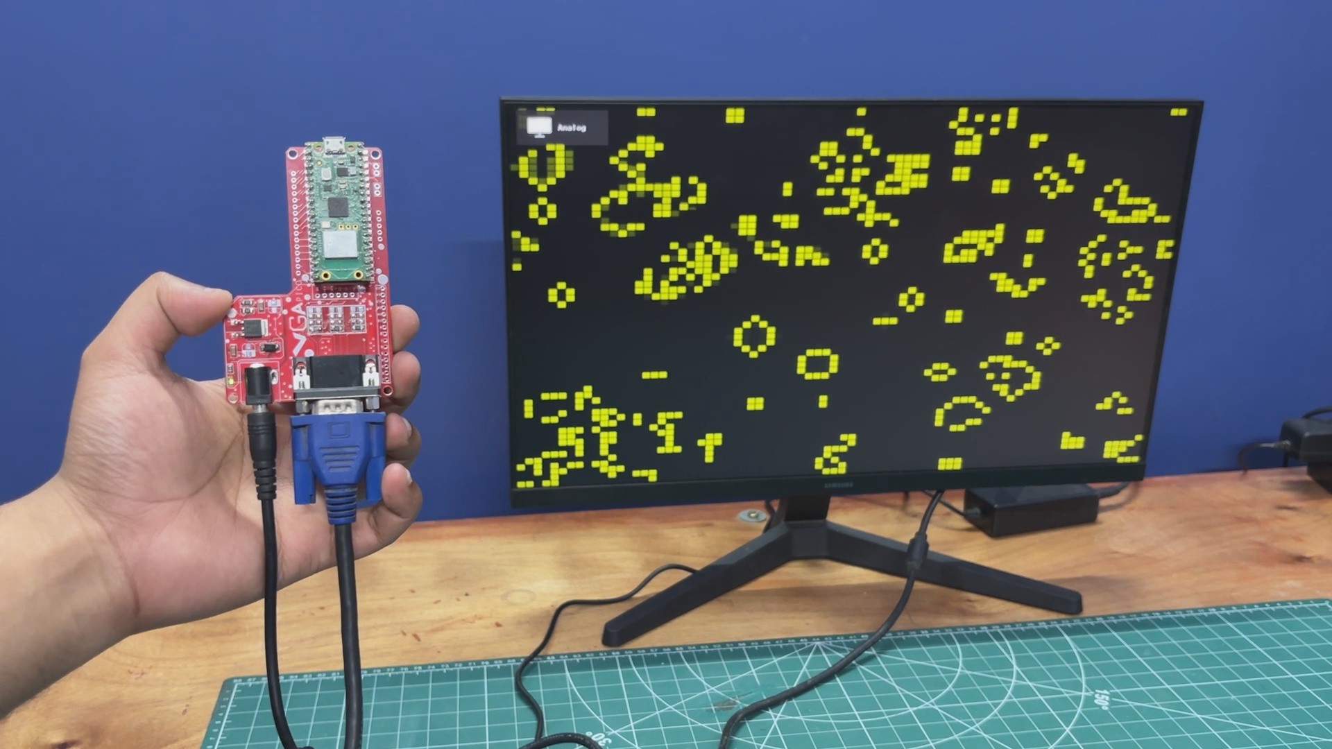
The whole project is loosely based around an existing VGA library for PICO, which was made to work with CRT monitors. I made some changes to it so it can be used with modern LCD VGA Monitors.
This article covers the complete build process of the PICO VGA Board and walks you through the whole code process.
HOW VGA PORT WORKS
Before starting this project, we first need to understand how VGA ports actually work. VGA, or Video Graphics Array, is an analog video interface that sends image data from a device, such as our Raspberry Pi Pico, to a monitor. Unlike HDMI or DisplayPort, VGA does not send digital packets; instead, it continuously streams voltages that represent colors and timing.
VGA uses three analog signals: Red, Green, and Blue. Each of these signal lines carries a voltage that typically ranges from 0 to 0.7V. At 0V, there is no intensity, and at 0.7V, the monitor displays full intensity.
By combining these three signal lines, the monitor recreates every pixel color. For example, if red is set to 0.7V while green and blue are at 0V, the result is pure red. If all three are set to 0.7V, the result is white.
In addition to RGB signals, VGA uses two digital signals: HSYNC (Horizontal Sync), which tells the monitor when a new line starts, and VSYNC (Vertical Sync), which indicates when a new frame begins.
The monitor draws the image by first rendering pixels from left to right in a single line. An HSYNC pulse then moves it to the next line, and this process repeats for all lines. A VSYNC pulse starts a new frame. This entire process happens approximately 60 times per second (60 Hz).
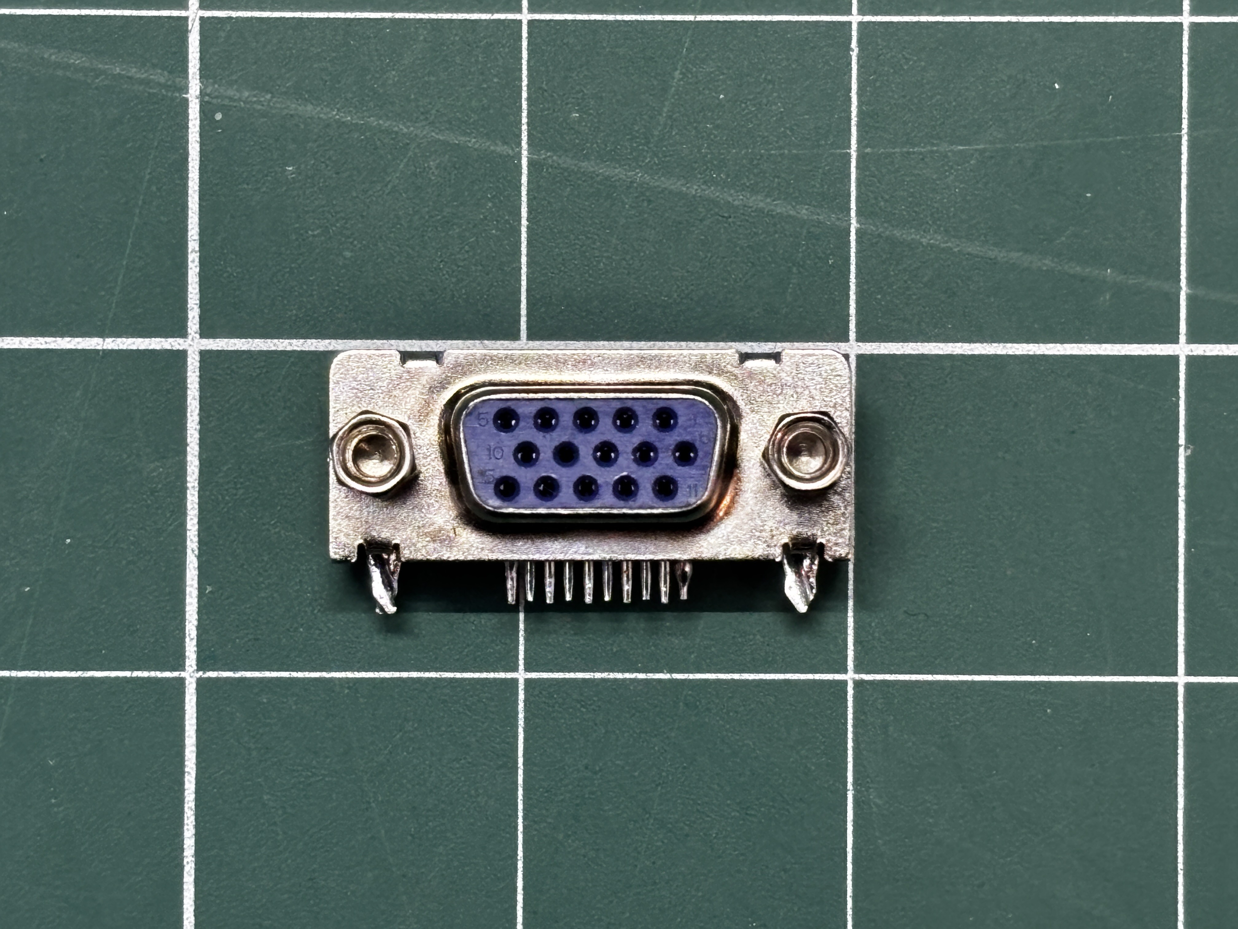
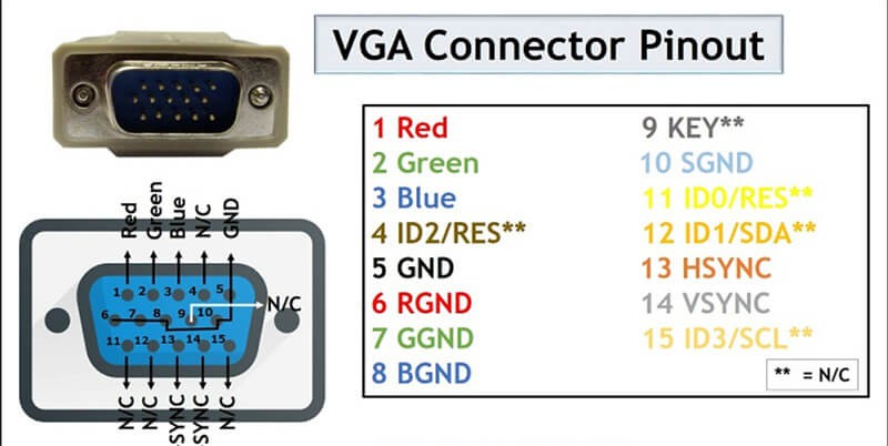
A VGA connector, also known as a D-Sub 15 (DB15) connector, consists of 15 pins. Pin 1 is for Red, Pin 2 for Green, Pin 3 for Blue, Pin 13 for HSYNC, and Pin 14 for VSYNC. The remaining pins are used for ground and other auxiliary functions.
PICO VGA LIBRARY
This project started when I came across a really interesting idea of using a VGA monitor with a Raspberry Pi Pico.
While exploring this, I found a Pico VGA library by Pancrea85. However, the original library was designed primarily for CRT monitors and didn’t work reliably with modern LCD VGA displays.
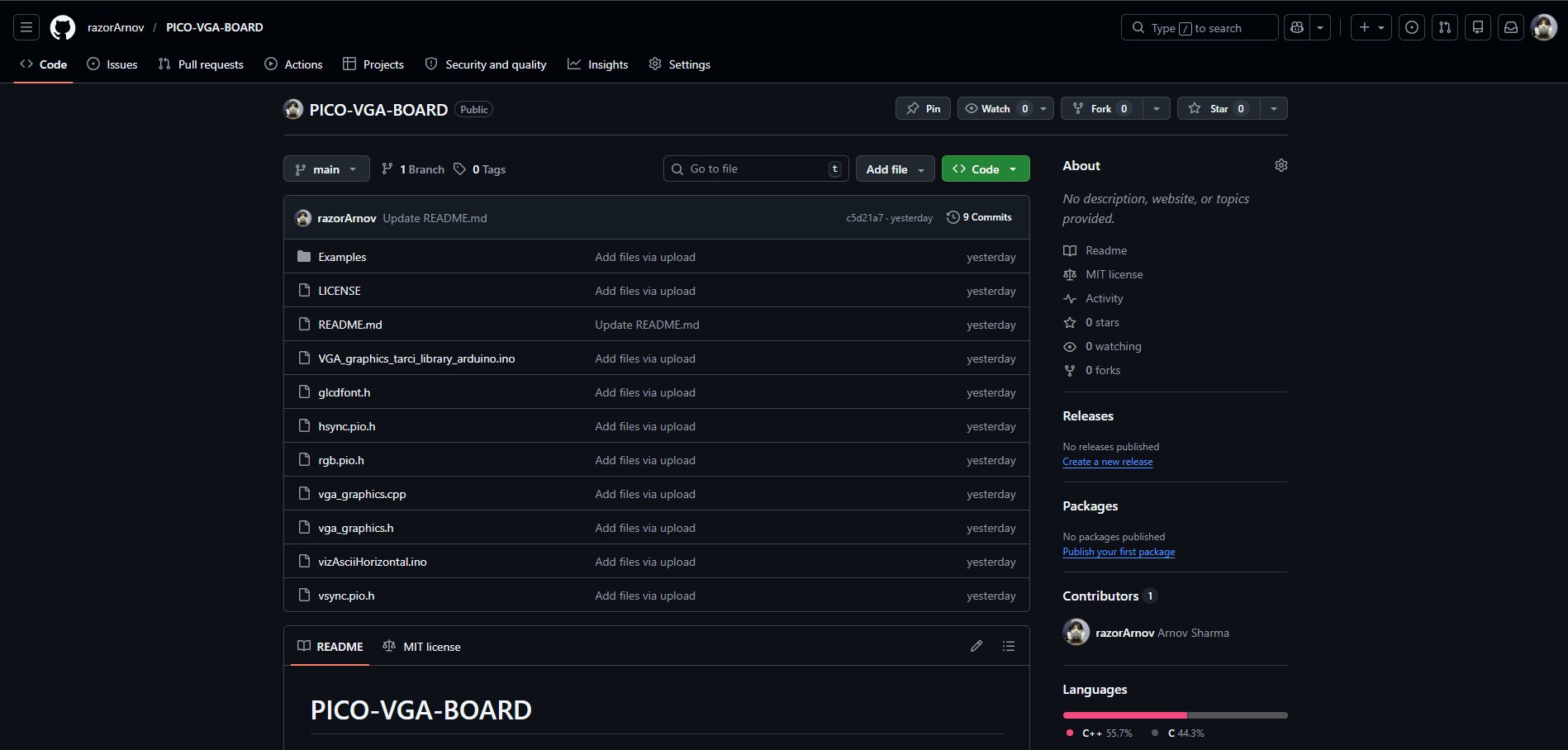
After making several modifications and adding a few example sketches, I created my own version of the library. This version is adapted for better compatibility with modern displays and can be easily installed and used from the GitHub link below.
https://github.com/razorArnov/PICO-VGA-BOARD
D-SUB15 VGA PORT & PICO BASIC CONNECTION
This is the basic wiring diagram used to interface a VGA monitor with the Raspberry Pi Pico.
- Pin 1 (Red) of the VGA connector is connected to GPIO18, with four 1kΩ resistors in parallel placed between them.
- Pin 2 (Green) is connected to GPIO19, with the same four 1kΩ resistors in parallel.
- Pin 3 (Blue) is connected to GPIO20, again using four 1kΩ resistors in parallel.
The resistance value controls brightness. Higher total resistance results in a dimmer image, while lower resistance increases brightness. An ideal combined resistance is typically in the 200–400Ω range.
- Pins 5, 6, 7, 8, and 10 are all connected to GND.
- Pin 13 (HSYNC) is connected to GPIO16.
- Pin 14 (VSYNC) is connected to GPIO17.
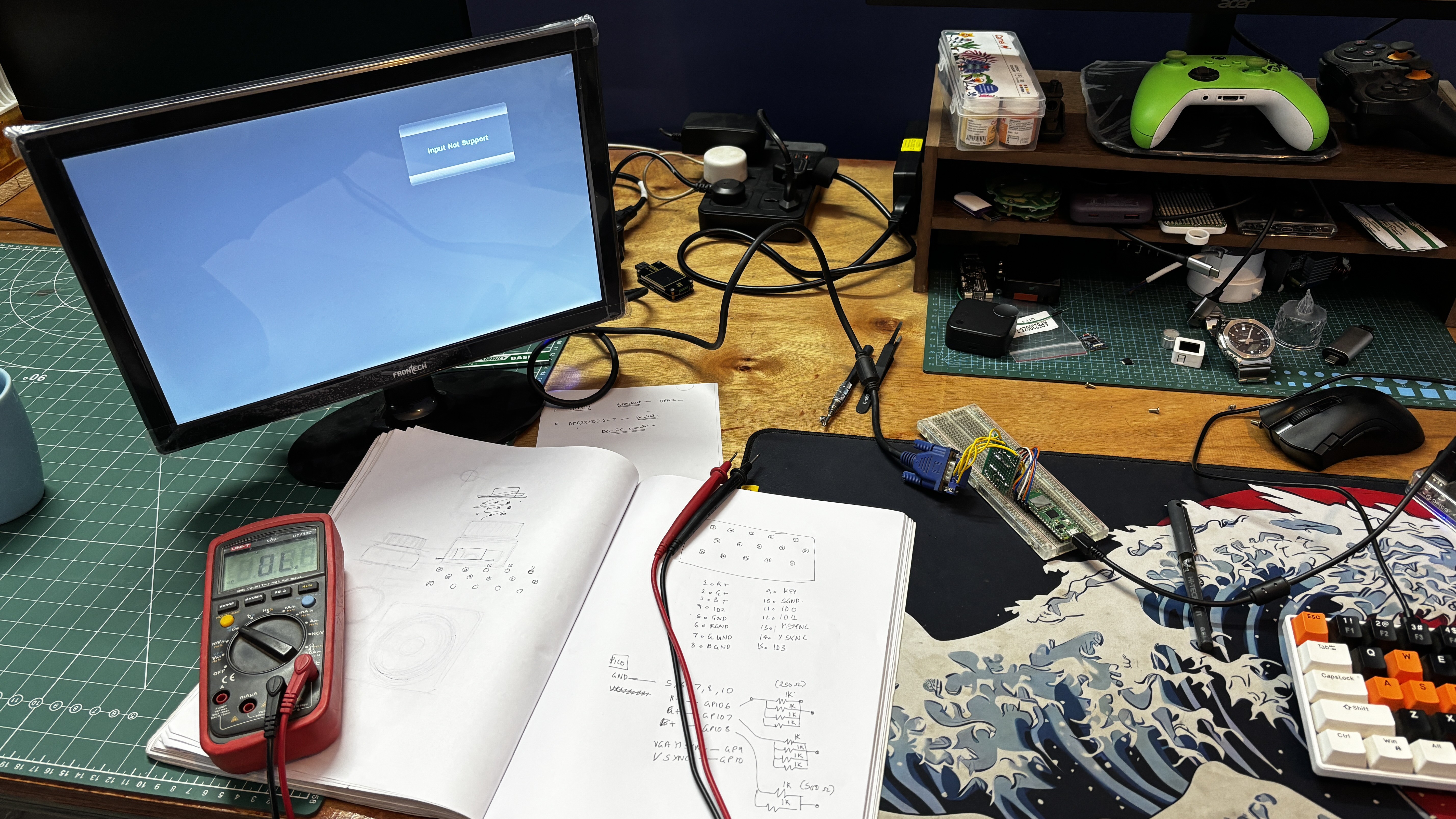
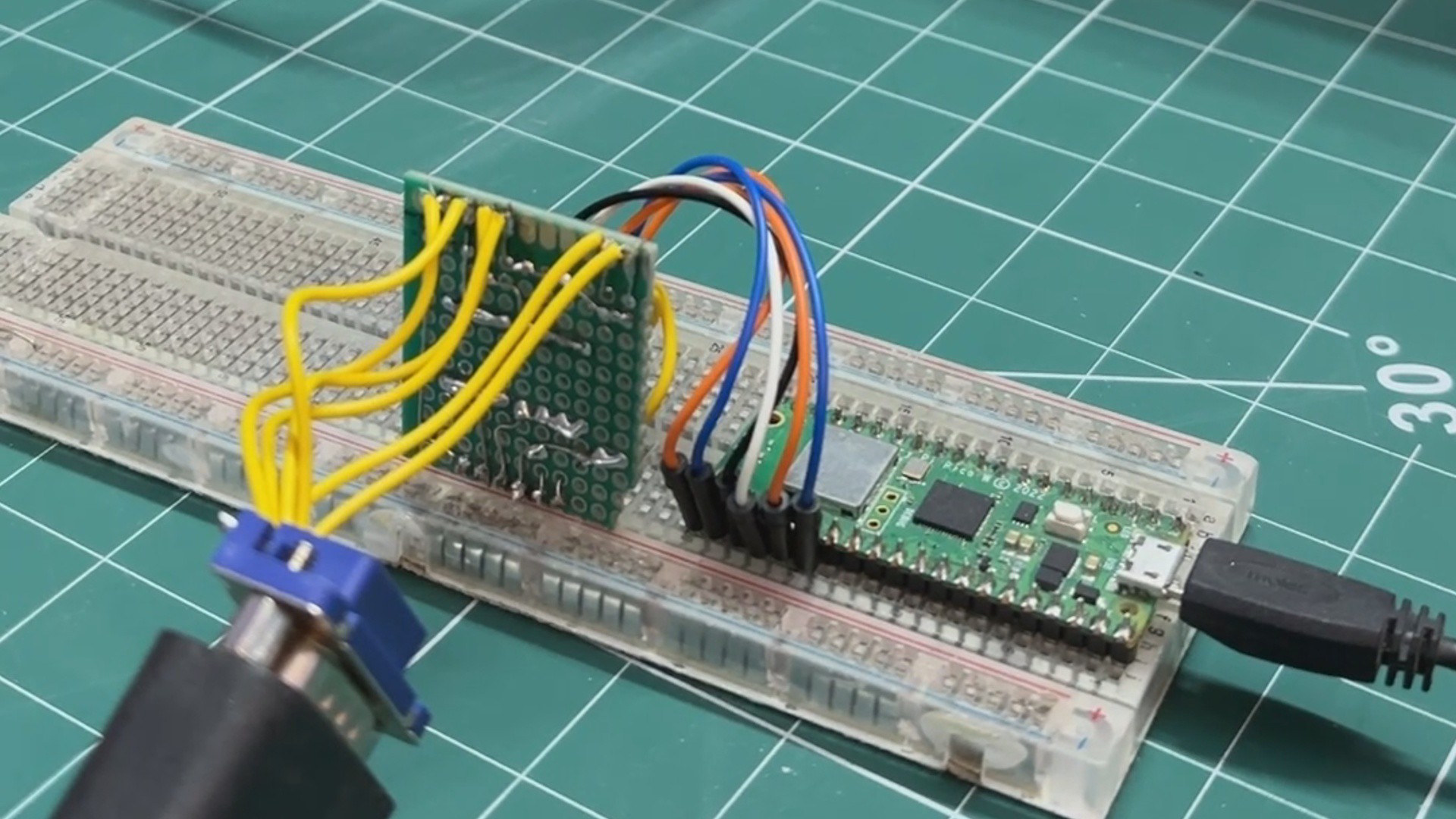
Using the VGA–Pico wiring diagram, we created a simple makeshift breadboard setup. A VGA connector was interfaced using jumper wires, which were connected to a prototype board containing resistor arrays for the RGB and sync lines. These signals were then linked to the Raspberry Pi Pico mounted on a breadboard, forming a complete test setup for VGA output.
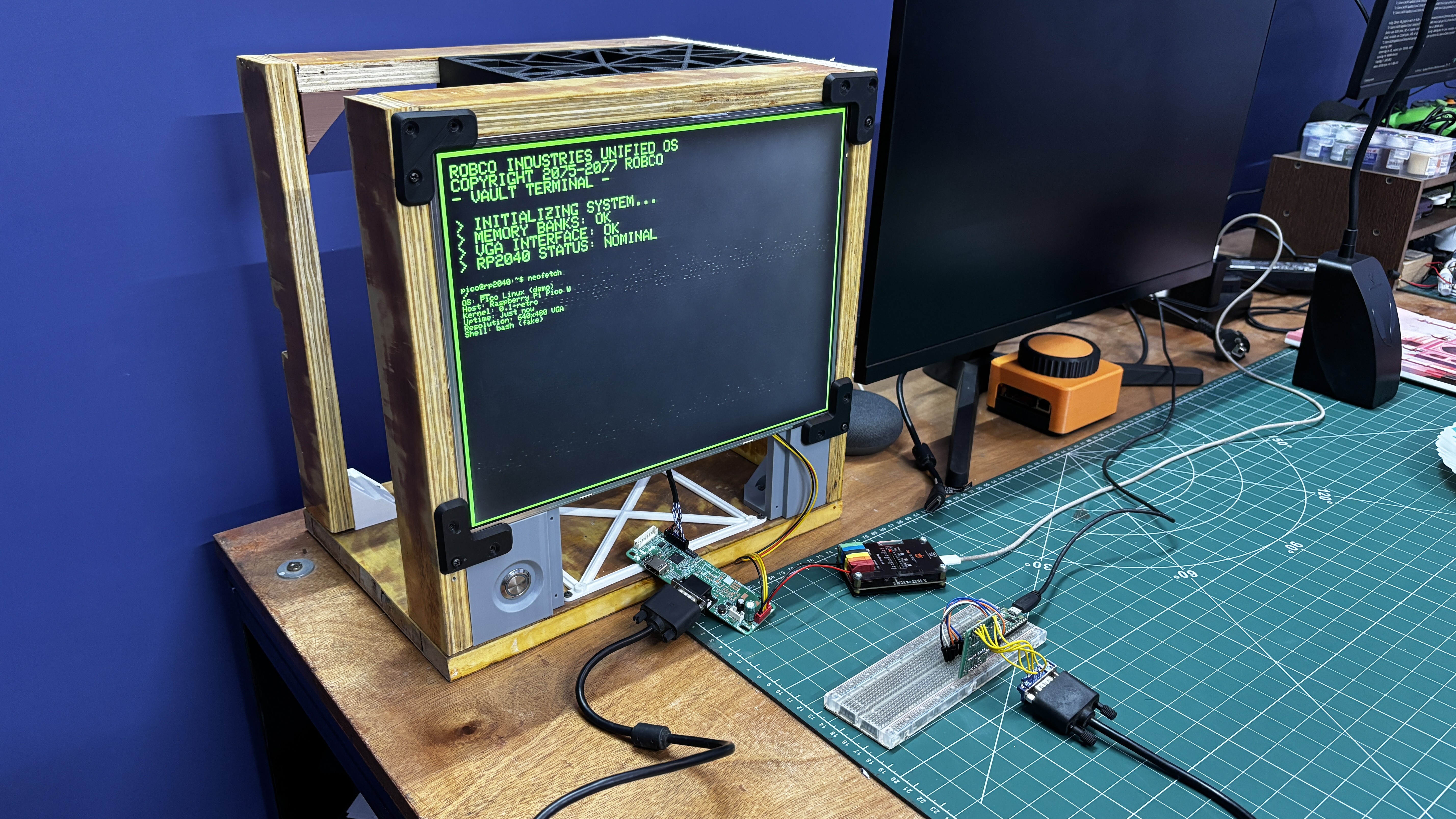
BREADBOARD SETUP DEMO
After completing the wiring, we uploaded a custom demo sketch that recreates a Linux-style terminal inspired by Fallout’s RobCo terminals, featuring the same iconic green color theme.
Below is the demo code.
#include "vga_graphics.h"

// ---------------- CONFIG ----------------
#define BORDER_THICKNESS 4
#define BORDER_MARGIN    14

// Fallout (big text)
#define BIG_CHAR_W 12
#define BIG_CHAR_H 16

// Linux (small text)
#define SMALL_CHAR_W 6
#define SMALL_CHAR_H 8

// Cursor
bool cursor_visible = true;
unsigned long last_blink = 0;

// ---------------- CURSORS ----------------
int big_col = 0;
int big_row = 0;

int small_col = 0;
int small_row = 18;   // start lower on screen

// ---------------- BORDER ----------------
void drawBorder() {
  for (int t = 0; t < BORDER_THICKNESS; t++) {
    drawHLine(t, t, screenWidth - 2*t, GREEN);
    drawHLine(t, screenHeight - 1 - t, screenWidth - 2*t, GREEN);
    drawVLine(t, t, screenHeight - 2*t, GREEN);
    drawVLine(screenWidth - 1 - t, t, screenHeight - 2*t, GREEN);
  }
}

// ---------------- TEXT HELPERS ----------------
void big_print(const char* s) {
  while (*s) {
    if (*s == '\n') {
      big_col = 0;
      big_row++;
    } else {
      drawChar(
        BORDER_MARGIN + big_col * BIG_CHAR_W,
        BORDER_MARGIN + big_row * BIG_CHAR_H,
        *s,
        GREEN,
        BLACK,
        2
      );
      big_col++;
    }
    s++;
  }
}

void small_print(const char* s) {
  while (*s) {
    if (*s == '\n') {
      small_col = 0;
      small_row++;
    } else {
      drawChar(
        BORDER_MARGIN + small_col * SMALL_CHAR_W,
        BORDER_MARGIN + small_row * SMALL_CHAR_H,
        *s,
        GREEN,
        BLACK,
        1
      );
      small_col++;
    }
    s++;
  }
}

// ---------------- BLINKING CURSOR ----------------
void draw_cursor() {
  int x = BORDER_MARGIN + big_col * BIG_CHAR_W;
  int y = BORDER_MARGIN + big_row * BIG_CHAR_H;

  if (cursor_visible) {
    fillRect(x, y + BIG_CHAR_H - 2, BIG_CHAR_W, 2, GREEN);
  } else {
    fillRect(x, y + BIG_CHAR_H - 2, BIG_CHAR_W, 2, BLACK);
  }
}

// ---------------- SETUP ----------------
void setup() {
  initVGA();
  clearScreen();
  drawBorder();

  // Fallout header (BIG)
  big_print("ROBCO INDUSTRIES UNIFIED OS\n");
  big_print("COPYRIGHT 2075-2077 ROBCO\n");
  big_print("- VAULT TERMINAL -\n\n");

  big_print("> INITIALIZING SYSTEM...\n");
  big_print("> MEMORY BANKS: OK\n");
  big_print("> VGA INTERFACE: OK\n");
  big_print("> RP2040 STATUS: NOMINAL\n\n");
  big_print("> ");

  // Linux / RPi info (SMALL)
  small_print("pico@rp2040:~$ neofetch\n\n");
  small_print("OS: Pico Linux (demo)\n");
  small_print("Host: Raspberry Pi Pico W\n");
  small_print("Kernel: 0.1-retro\n");
  small_print("Uptime: just now\n");
  small_print("Resolution: 640x480 VGA\n");
  small_print("Shell: bash (fake)\n");
}

// ---------------- LOOP ----------------
void loop() {
  unsigned long now = millis();
  if (now - last_blink > 500) {
    last_blink = now;
    cursor_visible = !cursor_visible;
    draw_cursor();
  }
}
Here's a small breakout for the code.
First we begin by defining Border thickness and spacing from edges.
#define BORDER_THICKNESS 4#define BORDER_MARGIN 14
Next, we added two font scales, BIG for the fallout header and SMALL for the terminal info.
#define BIG_CHAR_W 12#define BIG_CHAR_H 16#define SMALL_CHAR_W 6#define SMALL_CHAR_H 8
Here are the Cursor Variables, which are used to create a blinking cursor effect.
bool cursor_visible = true;unsigned long last_blink = 0;
This is for Text Position Tracking. small_row = 18 pushed the Linux test lower on the screen and prevents overlap with the big header.
int big_col = 0;int big_row = 0;int small_col = 0;int small_row = 18;
We use the void drawBorder() function for drawing a rectangular green border around texts. drawHLine() is for horizontal lines, drawVLine() is vertical lines.
Also, this loops to make the border thicker.
for (int t = 0; t < BORDER_THICKNESS; t++)
Using the below function, we are able to print large text. (scale 2)
void big_print(const char* s)
Similarly, using the below function, small texts are printed, and smaller fonts are used (scale 1).
void small_print(const char* s)
For Blinking Cursor, this draws a block-style underline cursor.
void draw_cursor()
If Visible, this draws green; if hidden, it erases.
fillRect(x, y + BIG_CHAR_H - 2, BIG_CHAR_W, 2, GREEN);
In Setup, VGA is initialized, Border is drawn, and every print job is done, from Big texts to small texts, all are printed in Setup.
initVGA();clearScreen();drawBorder();
Big Texts
big_print("ROBCO INDUSTRIES...");
Small Texts
small_print("pico@rp2040:~$ neofetch\n\n");
In the Loop, cursor blinking logic is being run continuously.
if (now - last_blink > 500)
After making sure that the breadboard setup is functioning nicely, we next move on to stage two of this project, which is to prepare a proper board for the setup.
PCB DESIGN
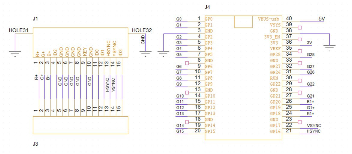
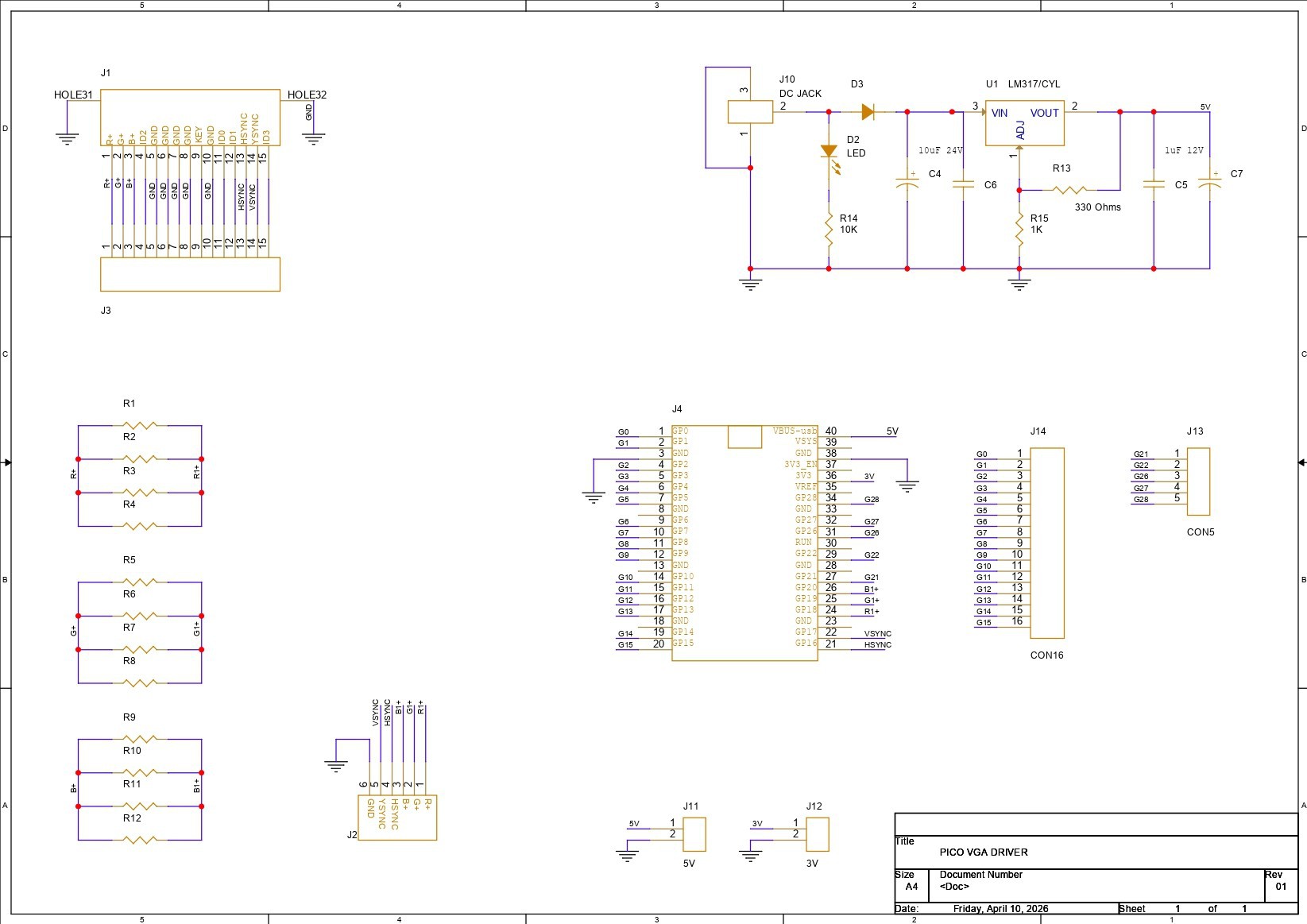
We begin the PCB design process by preparing the schematic first. Here, we recreated the connection of the D-Sub 15 connector with the Pico wiring. In this, we paired Pico GPIO18, GPIO19, and GPIO20 with Pin 1, Pin 2, and Pin 3 of the VGA connector, with three resistors placed in between.
We will be adding a single 330Ω resistor on each R, G, and B line. Each RGB line has three resistors connected in parallel, so we can easily adjust the resistance value by adding or removing any resistor. We just need to make sure all three resistor values in R, G, and B are the same.
Pin 13, which is HSYNC, is connected to GPIO16, and Pin 14, which is VSYNC, is connected to GPIO17. The Pins 5, 6, 7, 8, and 10 are all connected to GND.
We have also added a CON15 connector, which is linked to all VGA pins from Pin 1 to Pin 15, in case we need to break out each pin of the VGA D-Sub connector.
For the Pico, we have added a few connectors connected to unused GPIO pins so we can use these pins for future projects.
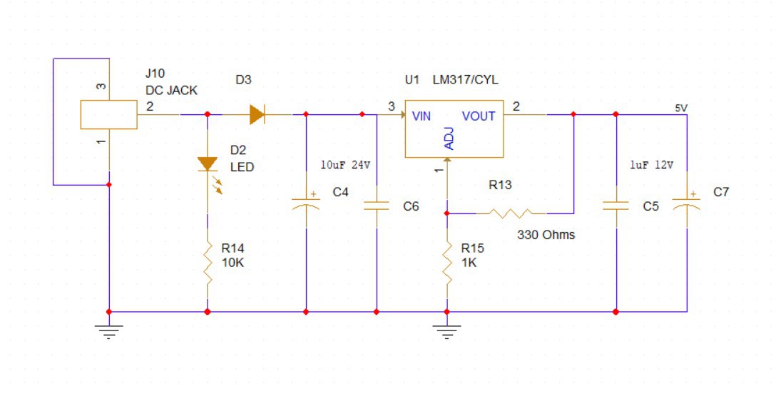
For power, we added an LM317, which is an adjustable three-pin positive voltage regulator capable of supplying more than 1.5A over an output voltage range of 1.25V to 37V.
https://www.ti.com/lit/ds/symlink/lm317.pdf
We have set up the LM317 in such a way that when we input 12V, we get a stable 5V for powering the Pico.
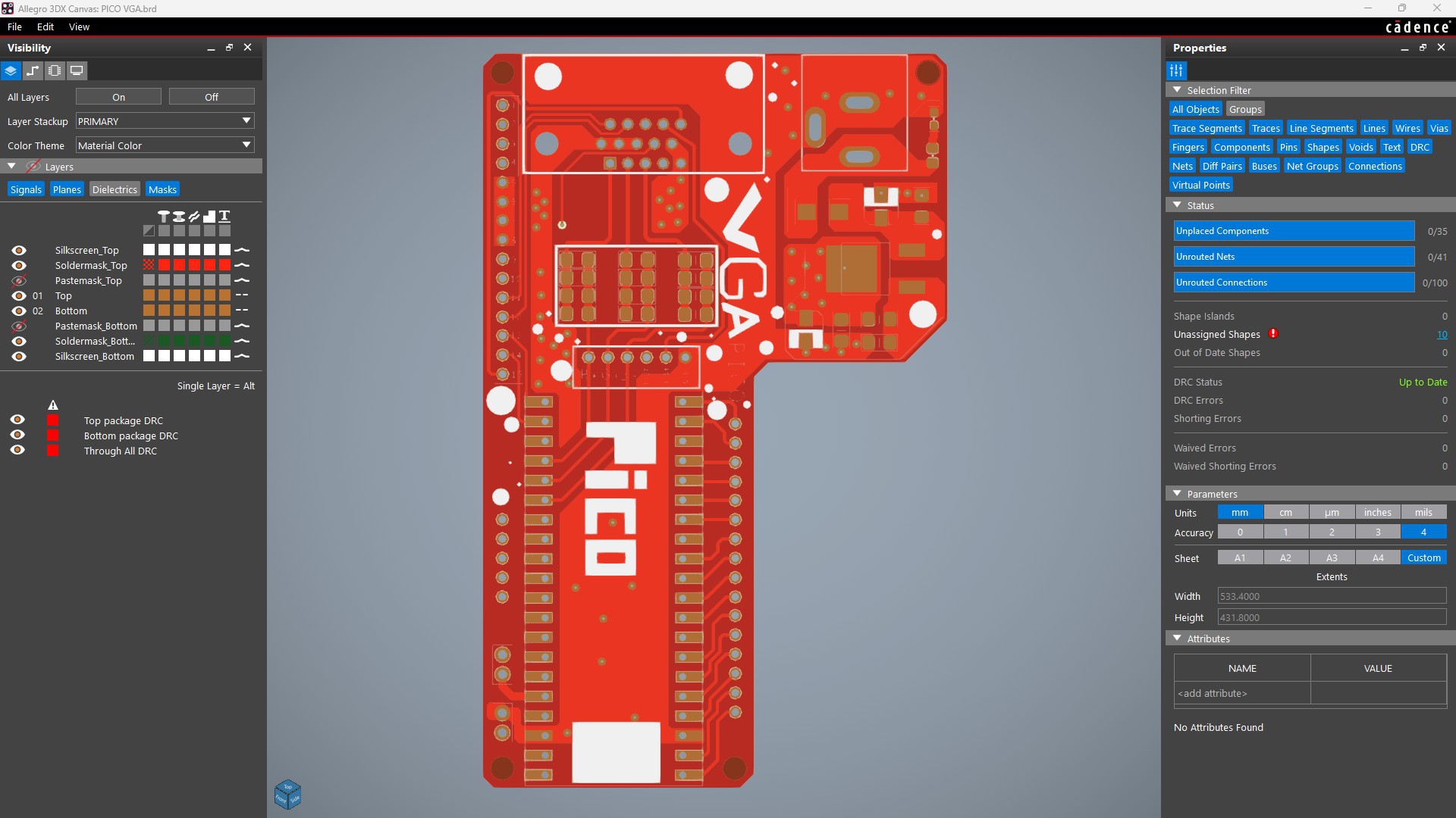
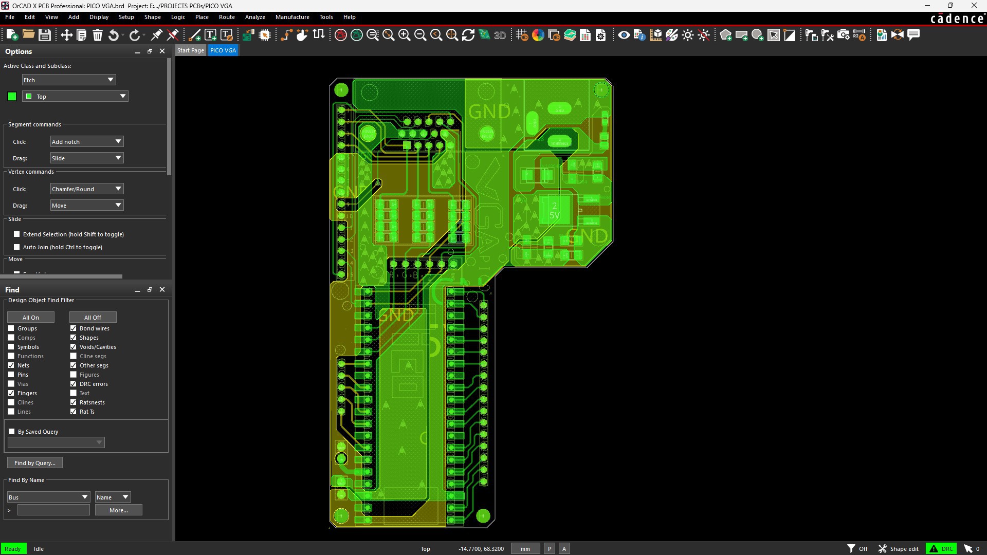
After completing the PCB schematic and preparing the PCB, we exported the Gerber data and sent it for manufacturing.
NextPCB PCB SERVICE
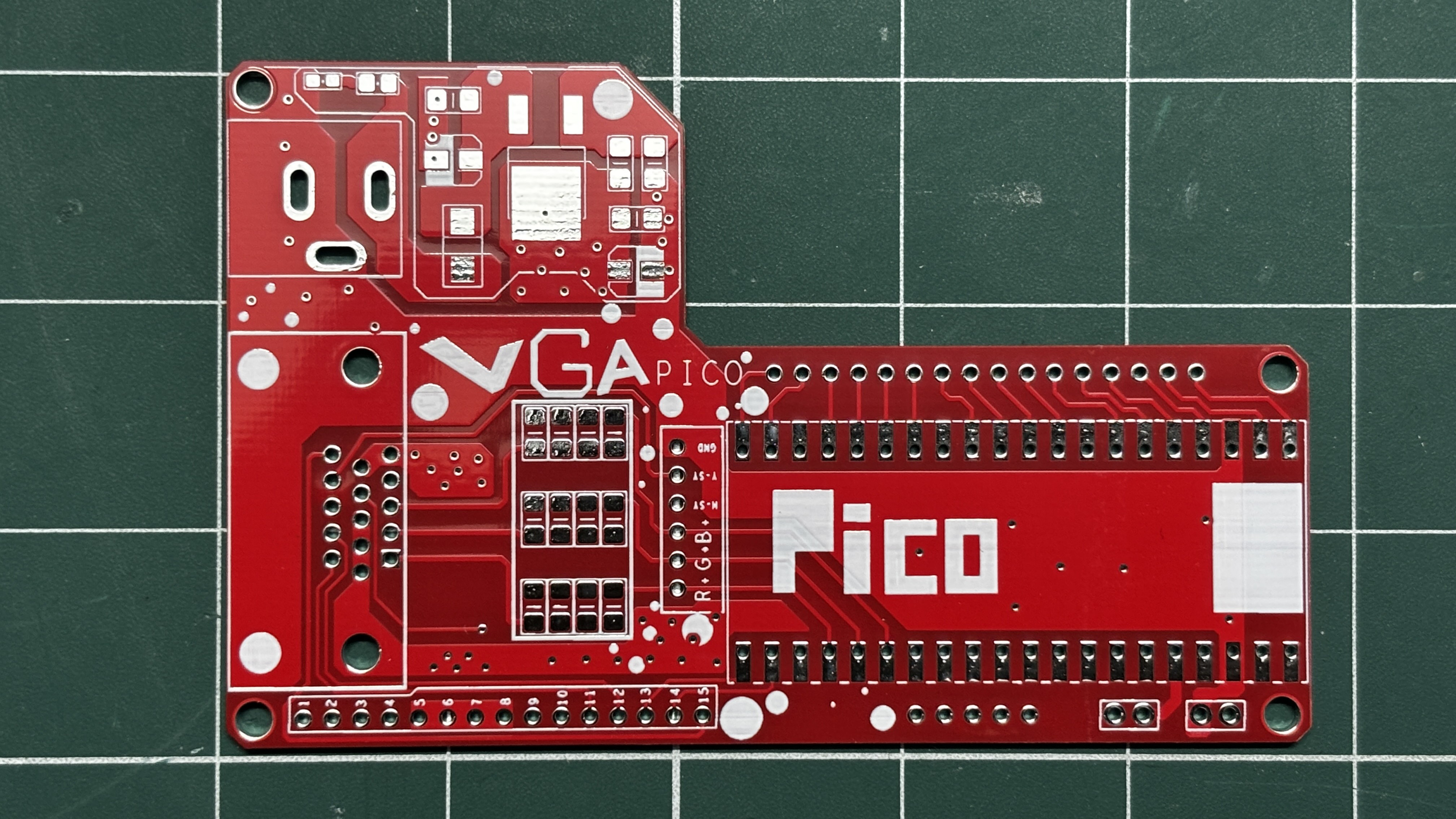
After completing the PCB design, Gerber data for PCB was sent to HQ NextPCB, and an order was placed for RED Solder mask boards with a white silkscreen.
After placing the order, the PCBs were received within a week, and the PCB quality was pretty great.
In addition, I have to bring in HQDFM to you, which helped me a lot through many projects. Huaqiu’s in-house engineers developed the free Design for Manufacturing software, HQDFM, revolutionizing how PCB designers visualize and verify their designs.
Take advantage of NextPCB's Accelerator campaign and get 2 free assembled RP2040-based PCBs for your innovative projects.
https://www.nextpcb.com/blog/rp2040-free-pcba-prototypes-nextpcb-accelerator
This offer covers all costs, including logistics, making it easier and more affordable to bring your ideas to life. SMT services can be expensive, but NextPCB is here to help you overcome that hurdle. Simply share your relevant project, and they'll take care of the rest. Don't miss out on this amazing opportunity to advance your tech creations!
HQDFM: Free Online Gerber Viewer and DFM Analysis Tool
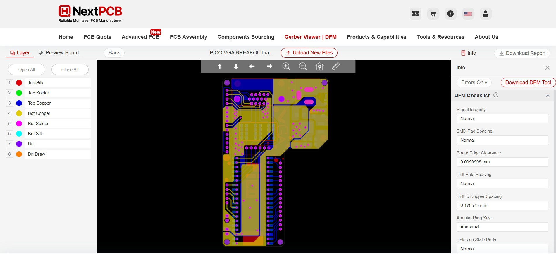
Also, NextPCB has its own Gerber Viewer and DFM analysis software.
Your designs are improved by their HQDFM software (DFM) services. Since I find it annoying to have to wait around for DFM reports from manufacturers, HQDFM is the most efficient method for performing a pre-event self-check.
This is what I see in the online Gerber Viewer. It's decent for a quick look, but not entirely clear. For full functionality—like detailed DFM analysis for PCBA—you’ll need to download the desktop software. The web version only offers a basic DFM report.
With comprehensive Design for Manufacture (DFM) analysis features, HQDFM is a free, sophisticated online PCB Gerber file viewer.
With over 15 years of industry experience, it offers valuable insights into advanced manufacturing processes. If you’re looking for reliable PCB services at a budget-friendly price, HQ NextPCB is definitely worth checking out.