 Sayan
SayanA synchronous buck converter is a DC-DC step-down topology that uses a MOSFET instead of a diode for rectification. The high-side MOSFET switches the input supply and the low-side MOSFET provides a low-resistance path during the off-cycle. This reduces conduction losses as compared to a diode. This improves efficiency, especially at higher currents. Proper gate driving and dead-time control is necessary to avoid short circuit. In this circuit, IR2104 takes care of the dead time (500ns fixed dead time). The switching duty cycle determines the output voltage. The LC filter smooths the output.
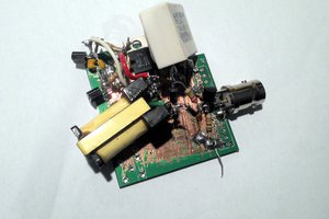
The converter is implemented using the IR2104 with external MOSFETs and reached 92% peak efficiency during testing( conditions: 12v input, approx. 7v, 2A output).I tested the setup using ESP32 using PWM of 19kHz and 12bits. The design works as expected but has some limitations. There is a backflow observed when the output voltage is higher than the input voltage(a very common issue with this topology; if somehow knows how to fix it, let me know). The control is not fully flexible due to the driver( fixed dead time and complementary switching of high side and low side) . Efficiency drops at low load conditions due to discontinuous conduction and switching losses. Since the IR2104 driver limits the control, it's difficult to improve efficiency during discontinuous conduction. I am working on replacing it with IR2110 which will enable full control over the converter.
Note: If you are building this circuit, be aware of the limitations mentioned. Also, a good synchronous buck converter can be implemented with dedicated ics widely available(eg. TPS40007). The goal of this project was to understand the concepts in depth and have a little bit fun of DIY.
 Jenny List
 Evangelos Petrongonas
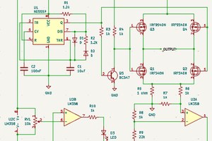
 electronicsworkshops