 Anders Dinsen
Published circuits for doing shutter speed measurement essentially all work the same:
- A photo transistor is placed right behind the camera with the film door open looking into the shutter.
- The transistor reacts to light let through the shutter and converts that into an electrical current.
- The current is converted into a voltage by a resistor and the pulse width measured on the oscilloscope.
- One or more LED's on the lens-side of the camera work as light source.
- As long as the photo transistor is in darkness, it remains cut-off with no current flowing through it.
- When the photo transistor is illuminated, it begins to conduct and sources a current proportional to the amount of light reaching the chip.
- If the light source is strong enough the transistor may eventually be driven into saturation.
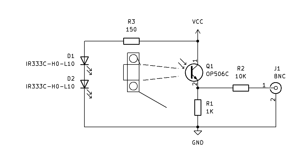
The schematic diagram of our circuit is shown below.
We have taken a slightly different approach than others as instead of fitting the transistor right behind the shutter, we put it in a box deep enough to allow the transistor to see all 35mm width of the shutter, and we use a storage oscilloscope to measure how the opening of the shutter affects the light coming through.
The OP506C has a relatively narrow field of light sensitivty of about 20 degrees. To ensure reasonable coverage of the full 35mm frame, we located the transistor 100 mm off the film plane:
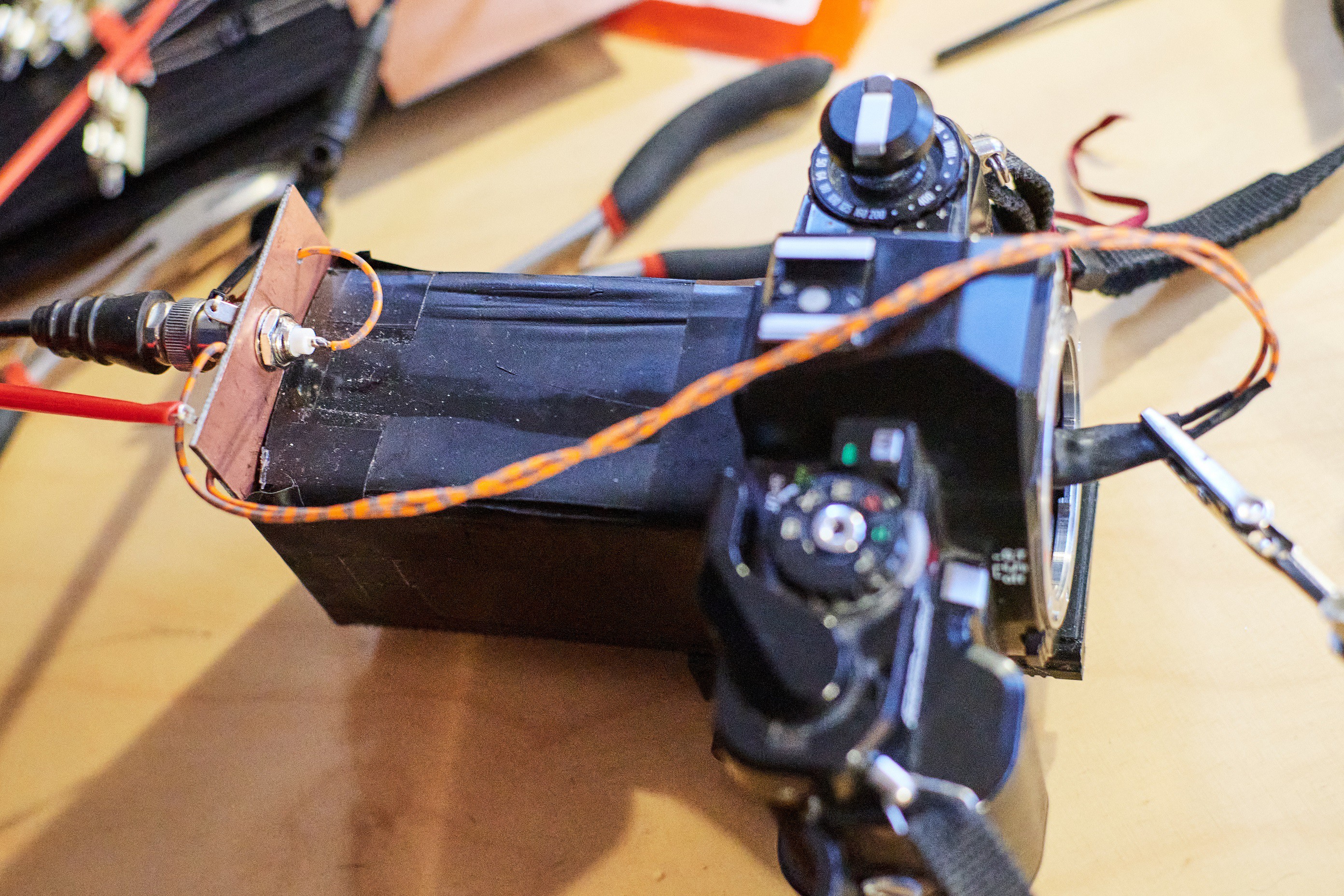
Our box is made of black PELD plastic sheet.
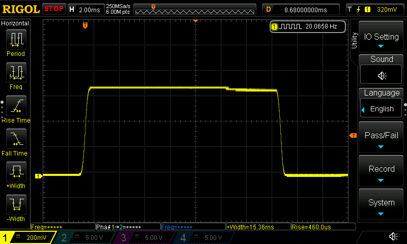
Due to the physical distance between the LED's and the transistor. and the relatively low value of R1, the transistor is never driven into saturation but produces a signal of up to about 500 mV on the scope. This gave us a signal like this on our Chinon CP5S at 1/60 setting:
Here are some further details of our circuit:
- VCC = 5V results in a LED current of about 20 mA. The IR333C LED's can handle up to 100 mA.
- R1 has been chosen to minimize delays in the signal introduced in the resopnse time of Q1. With 1K, rise/fall times are about 20 us. According to the data sheet, rise/fall times increase progressively with the value of R1.
- R2 acts as a short circuit protection so we don't blow the transistor if the output is shorted to ground.
- Two LED's D1 and D2 are connected in series to give more light and a wider light pattern maching the 35 mm opening of the shutter.
- The OP506C is not really a perfect match for the IR333C-H0-L10's as it has its best spectral response at about 860 nm, whereas the LED's we use have peak at 940 nm. However, the sensitivity of the transistor is only down to 80% because of that.
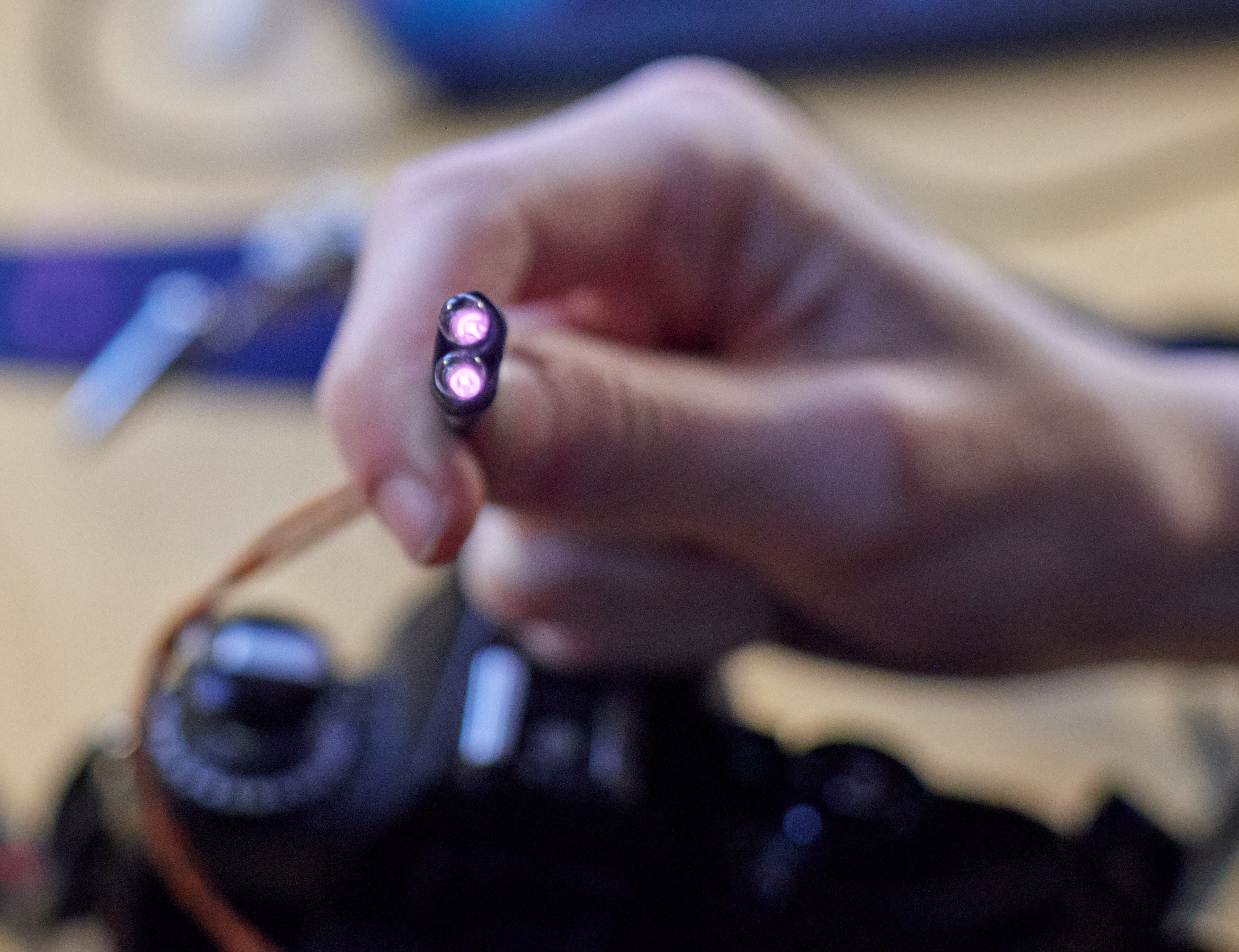
Note that 940 nm light is invisible so we can't actually see the light emitted by the LED's, but in our Nikon D500 camera, it shows as purple:

 James Cannan
 bornach
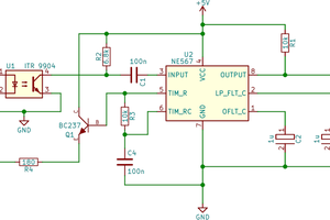
 Rainer Glaschick
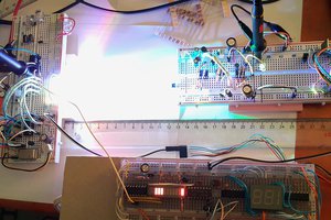
 Jovan
Jovan