 mircemk
Some time ago I presented you a project for a 3W stereo tube amplifier with a GU32 output vacuum tube. This time I will present you a way to make a quality stereo Tube preamplifier with three selectable inputs with ECC83 vacuum tubes. The circuit diagram is taken from a local electronics magazine "Emiter" from 2011 and the author of the project was Mr. Emilian Iljoski.
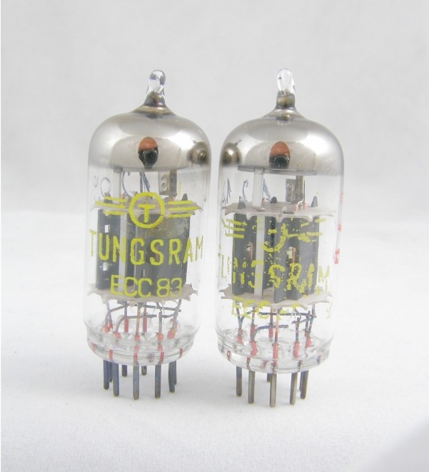
From this project I will use only the preamplifier part with minor modifications and I will implement the power supply in a slightly different way. The heart of the preamplifier are the well-known ECC83 tubes that are widely used in quality branded audio preamplifier stages.
This project is sponsored by PCBWay. From concept to production, PCBWay provide cutting-edge electronic design solutions for global innovators, Including hardware design, software development, mechanical design, product testing and certification. PCBWayengineering team consists of experienced engineers in electronics, embedded systems, and product development. They successfully delivered hundreds of projects across industries such as medical devices, industrial automation, consumer electronics, smart home, and IoT.

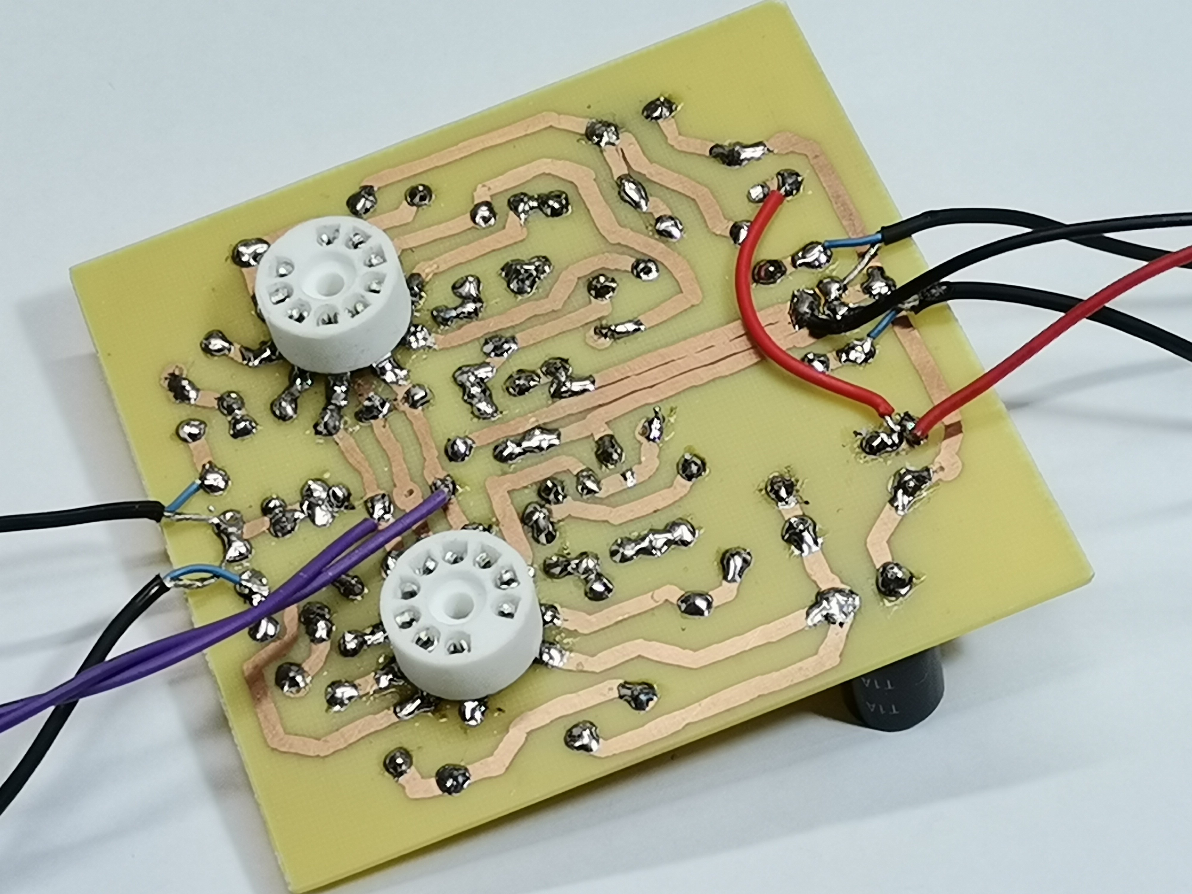
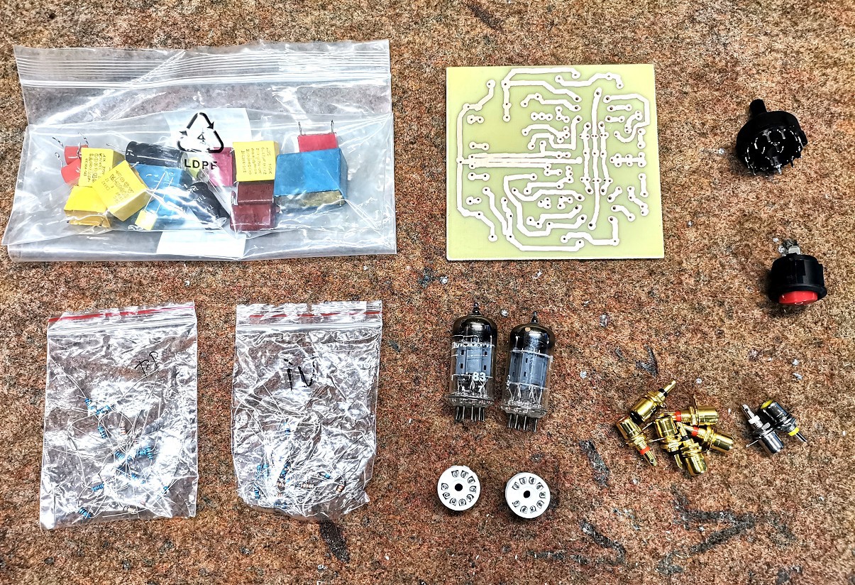
The original project contains a number of characteristic elements that are relatively difficult to obtain, but I tried to replace them with standard available components without major losses in quality. At the end of the text, the original circuit diagram for one channel is given, and the other channel is identical. I made the PCB for this prototype like in the old days by drawing with a permanent marker.
In almost all tube projects, the most difficult part to purchase and make is the power supply stage. This project in particular uses a 250V DC power supply plus 12V for heating the cathodes of the tubes. I solved this in a very easy and elegant way with the help of a cheap DC-DC boost converter.
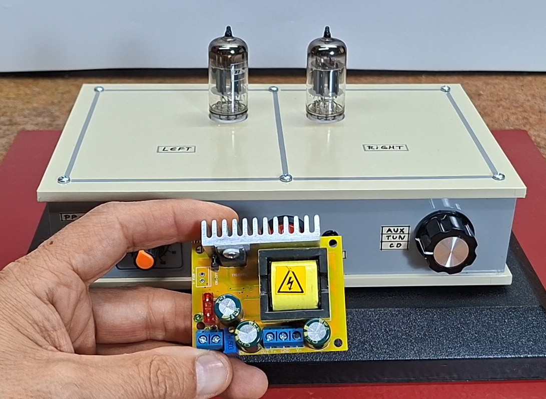
This preamplifier does not require high currents, so this converter is ideal for this purpose. The input voltage the converter is 12V and the same voltage is used for heating the tubes. At the output of the converter, we set a voltage of exactly 250V using this small multiturn potentiometer. Now let's look inside the preamplifier. In one part there is the DC-DC module which is desirable to be shielded to avoid interference with the preamplifier. Also the preamplifier PCB as well as the input section should be shielded for the previously mentioned reasons.
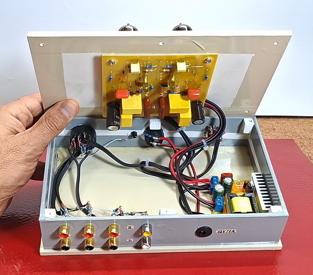
The coaxial cables used should be as high quality and short as possible. For the same reason the voltage dividers are made directly on the input connectors themselves. I use a 2x6 switch to select the inputs. The original project contains an attenuator instead of a potentiometer, but for the sake of economy and simplicity I decided to use a potentiometer.
The original project is titled High-End audio preamplifier, which is confirmed by the measurements performed, but I did not have such strict criteria for this particular project and my goal was a proof of work but also a relatively good mid-high class preamplifier.
Here are the measured technical characteristics and the subjective description of the sound quality from the author's side:
- Frequency range: 20Hz -100kHz (+/-3dB); 32Hz-20kHz (+/-1dB)
- Distortion: Second harmonic 0.8%, Third harmonic 0.1%, Fourth harmonic 0.3%
- Signal/Noise Ratio: 81dB(A)
- Channel Crosstalk 78dB at 1kHz
Sound characteristics: Fills the room with a pleasant and soft sound. Very good reproduction of the midrange with excellent separation of wind instruments. A small dose of undefined sound image in string instruments. Pleasantly surprising is the excellent dynamics of the midrange and high tones.
At the time of production, I did not have enough quality MKP capacitors, but I will certainly purchase and install them in place of the standard ones in the future. Also, the tubes I use in this project were taken...