 t.oster92
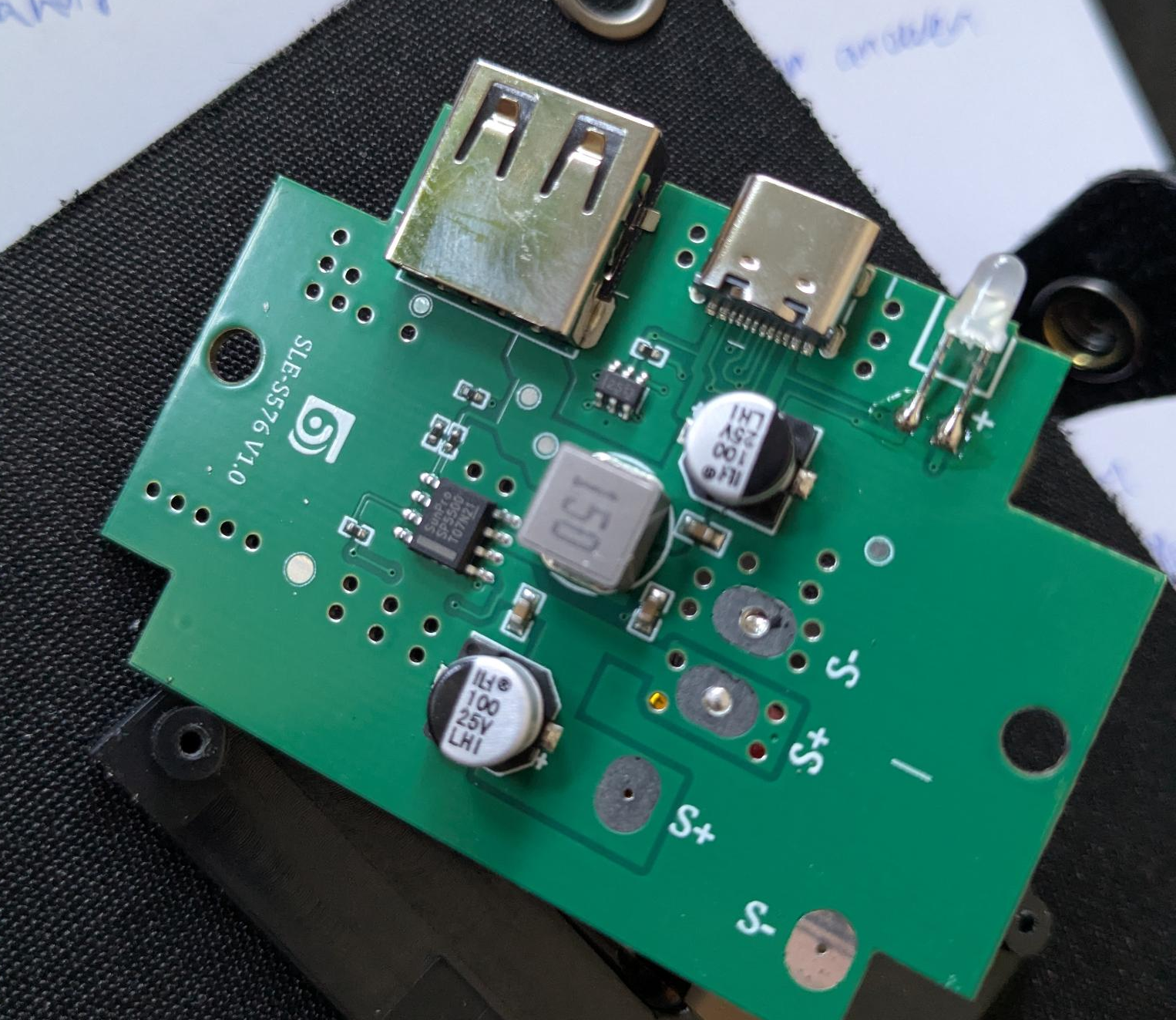
So: First, let's have a look inside. The PCB shows a chip that was marked as "SunPlus" - no chance to find any matching datasheet.
So, i let some AI tools suggest what could be inside this chip - probably it was rebranded, therefore i had to find promising candidates, and compare their actual pinouts.
I found that the MP2303 buck converter would match the layout quite well, and the inductor suggested in the datasheet has the exact same value of the one built into the panel.
Well, the MP2303 goes up to 3A only - and when close to that, it is probably also going to overheat soon, as it has 125mOhm switch resistance. At 3A, this already amounts to a Watt - an awful lot for a small SOIC package.
And judging by that, there was no way i could use this exact IC in order to deliver the 4A promised to me. Searching for pin-compatible replacements also left me without results.
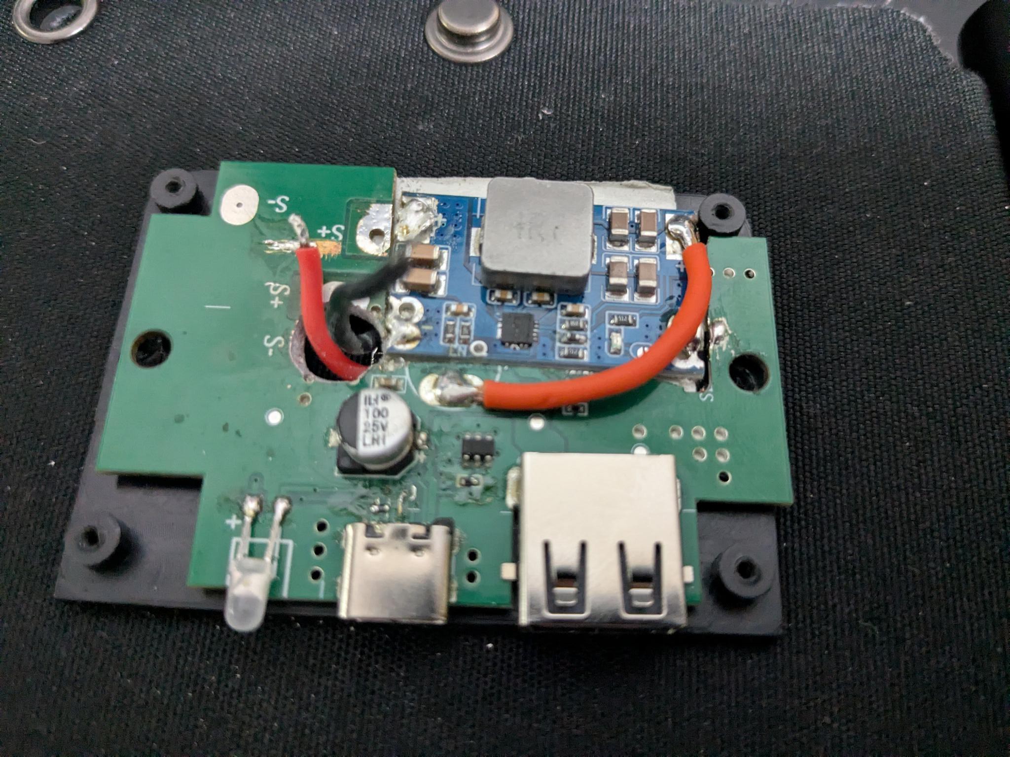
So, i did what sounds like a real promising idea: I searched the web for cheap 5A buck converters. I set my mind on just throwing them in there, in hope that this would work. I got some Mini560 boards for a few bucks. To be continued...
 OzQube
 Markus Loeffler
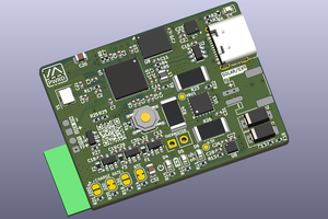
 dj505
dj505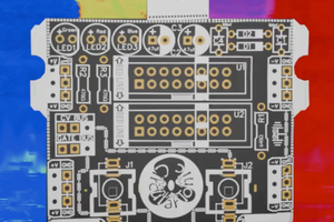
 Neil Mundt