 Andrea Console
Principle of Operation
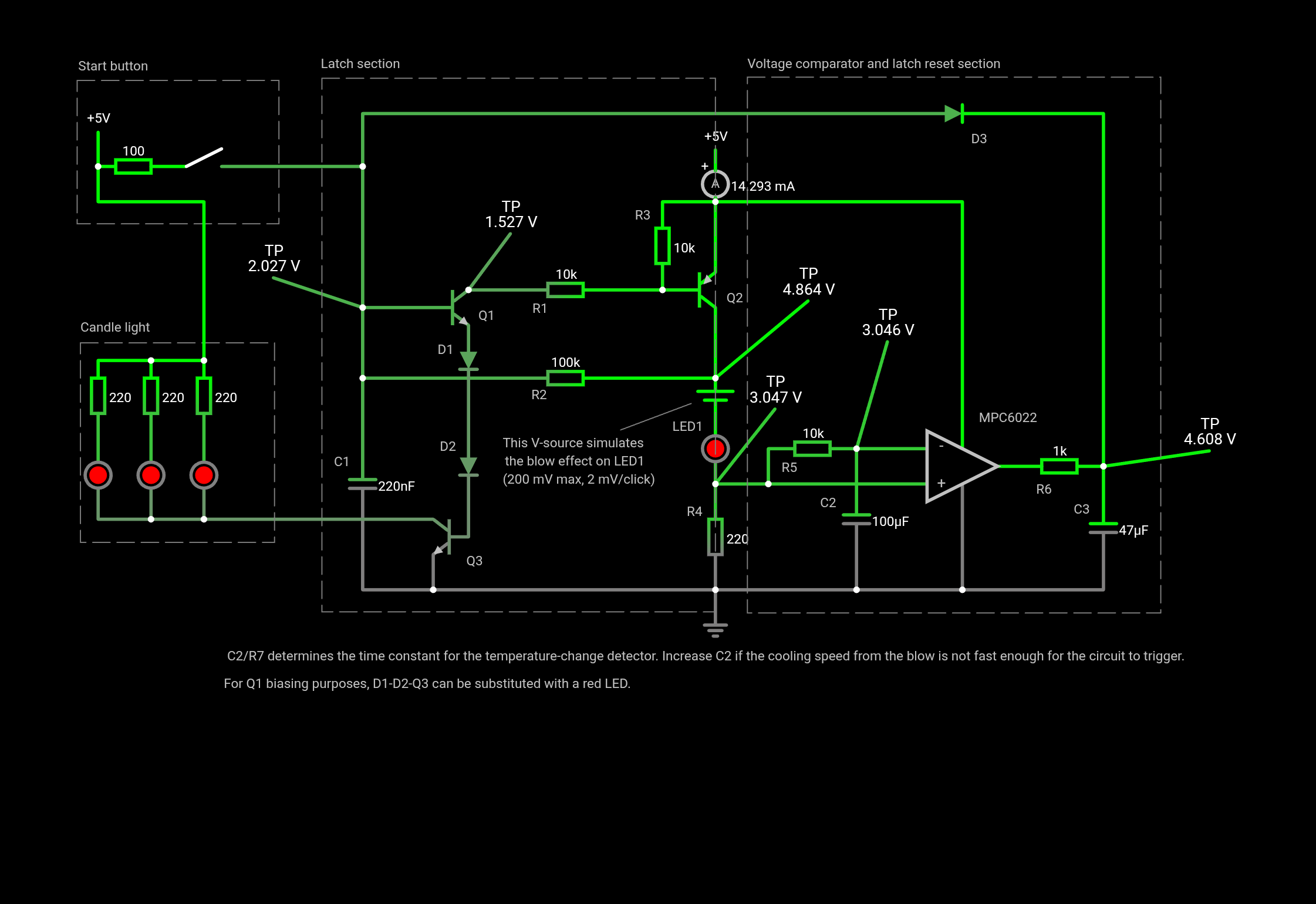
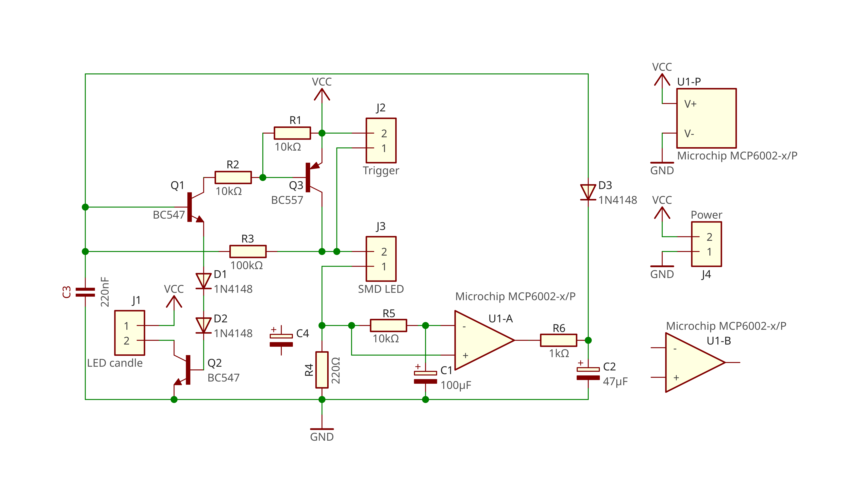
The circuit consists of two main sections: a latch that keeps the candle lit once triggered by a push button, and a comparator that monitors the voltage across the current-limiting resistor of the sensing LED (R4) and compares it to the reference stored in a 100 µF capacitor (C2). The voltage across C2 slowly follows the voltage across R4 thanks to R5. When the LED is cooled by airflow (i.e. when you blow on it), its forward voltage increases quickly but slightly. As a result, the voltage across R4 decreases accordingly.
When this happens, the op-amp detects that the voltage at its inverting input has fallen below that at the non-inverting input, causing the output to switch low. This transition resets the latch and turns the candle off.
Additional Details
- C1 prevents accidental latch activation by filtering transients on the push-button input.
- C3 filters noise at the op-amp output. This is critical because, when the voltage across C2 approaches that across R4, the comparator can oscillate. A sufficiently large low-pass filter stabilises the output around mid-supply (~2.5 V), preventing unintended latch resets.
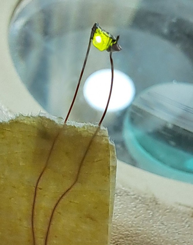
- LED1, the blow sensor, is a small SMD LED mounted on thin wires to minimise thermal mass and improve airflow sensitivity.
- Q3 is used to drive a higher-power light source; in the final version, it controls the main LED of a commercial electronic candle.

 Burkhard Kainka
 w_k_fay