SnoWHandS
We thought it would be fun to make an annoying insect that can sit inconspicuously in a room and randomly chirp when its absorbed enough light.
To get there, we needed a oscillator and energy harvester to bring this whimsical idea to life.
The Oscillator
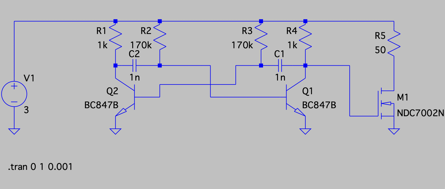
We discovered this oscillator circuit on Hackaday and thought it was neat how it leveraged transistors in a unconventional way to make an oscillator. We simulated and built this circuit on protoboard and managed to get it working!
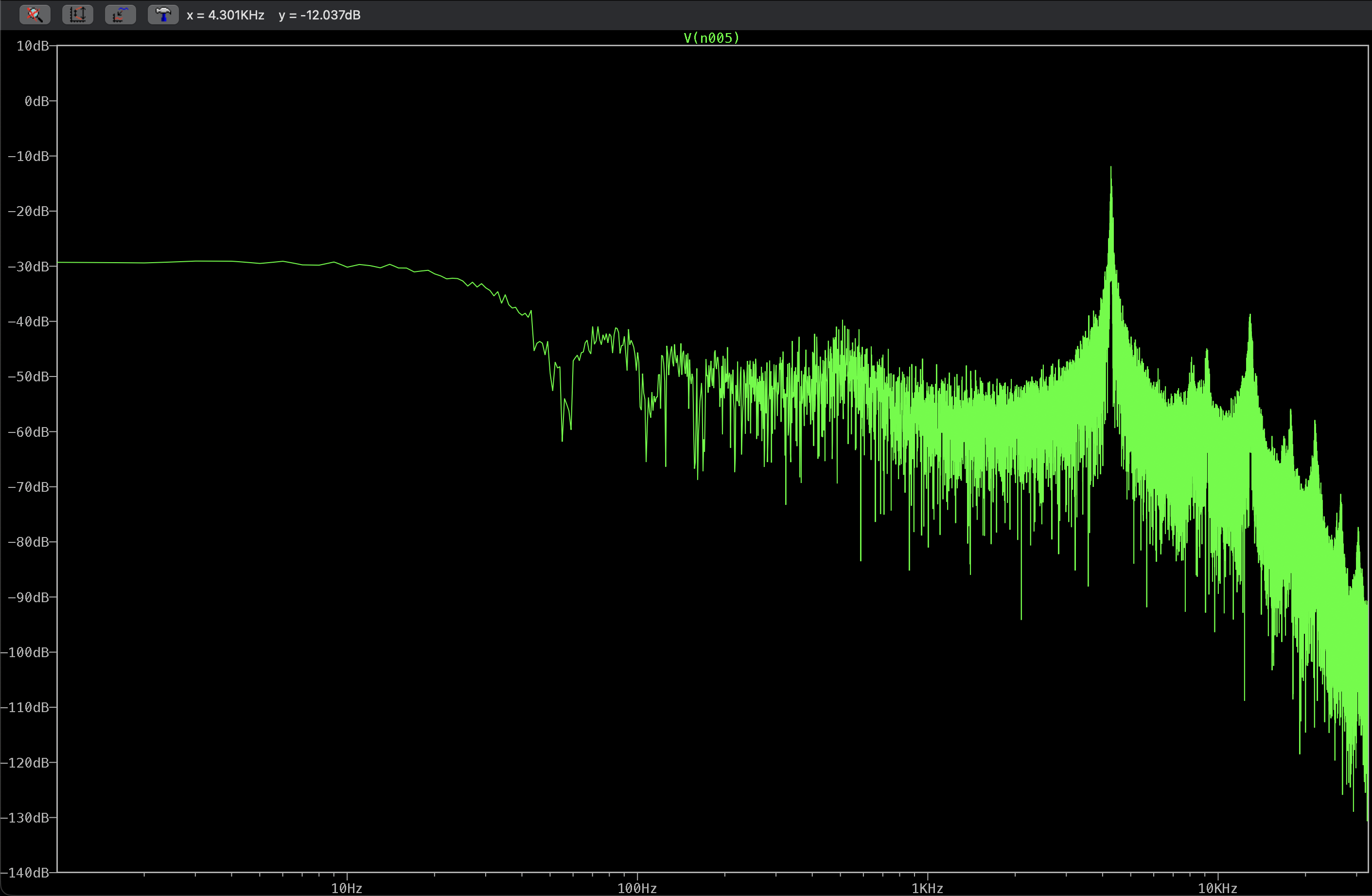
 The FFT of the simulated output of this circuit getting 4.3kHz
We initially did some calculations to get the oscillator to the right ball park but soon discovered that the particular characteristics of the NPN transistors effect the frequency that it oscillates at! We discovered this when we tried changing the design to match the transistors we had on hand (BC847).
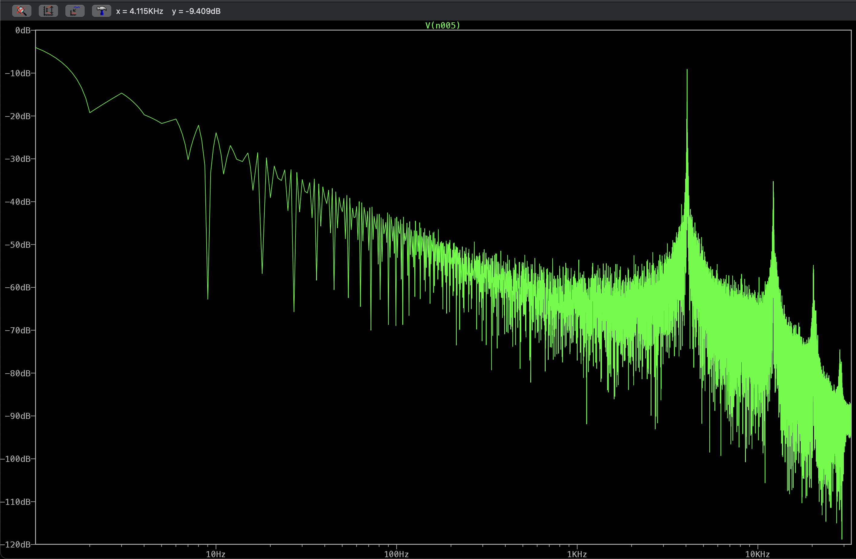
We are hitting 4.115kHz on the peak of the FFT with the BC847 compared to 4.3kHz on the 2N2222 model.
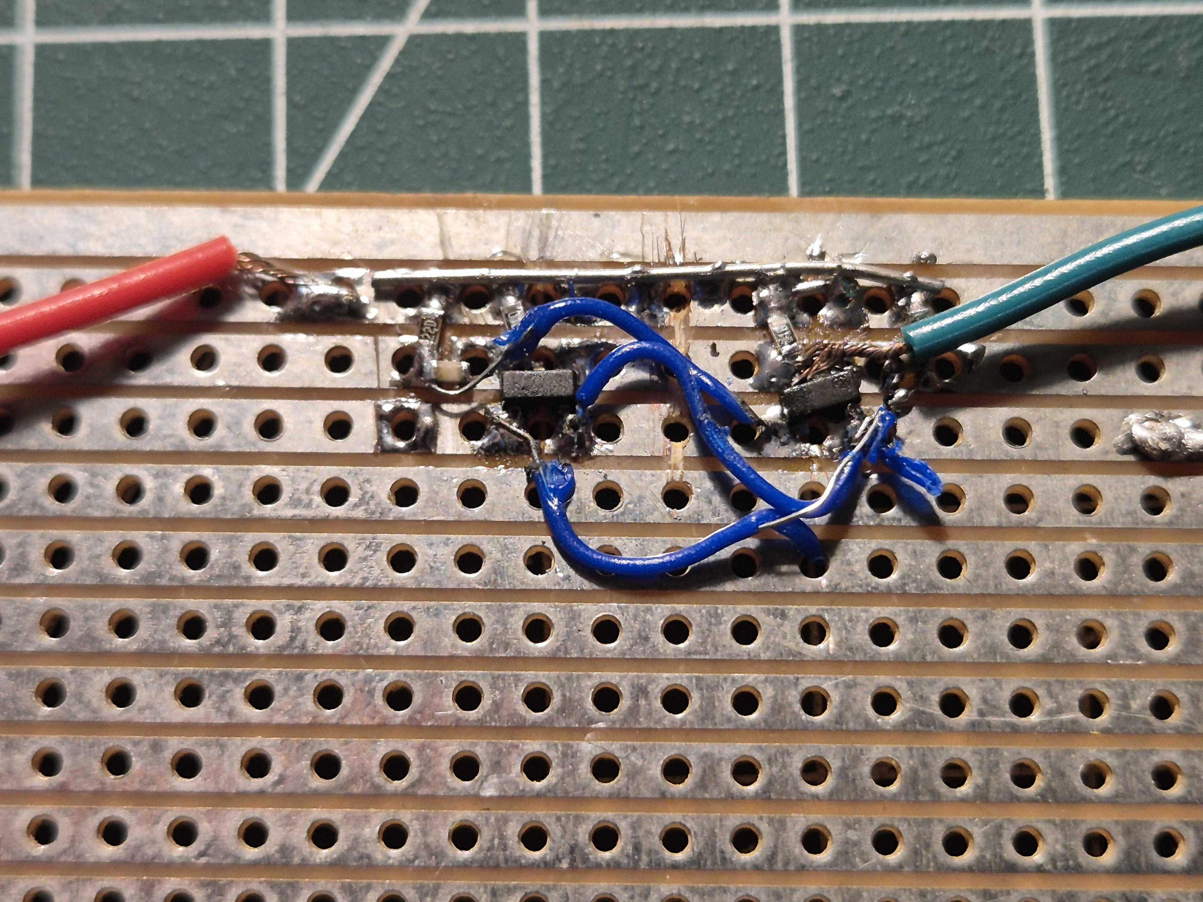
Here's the protoboard circuit that we managed to get to oscillate! We only had SMT parts available so we soldered up some 0402 resistors & SOT-23 BC847 NPN transistors and got successful oscillation!
Solar situation:
We had some prior experience with the BQ25505 energy harvester chip and since it can turn on at low voltages (0.6V cold start) it should work great for indoor solar.
The initial thinking for solar cells was to use BPW34 photodiodes which was inspired by this photodiode powered BLE chip. This made sense to go on the wings and it was the initial starting point of the project concept as it would look cool and capture plenty of light while the blue shade would add some nice contrast to the design.

After exploring the power we'd get with the photodiodes, it seemed less feasible. As an option, we kept the photodiodes on the main board design but depopulated it and rather went with KXOB25-03X4F-TB to make it more feasible to achieve its ambitious goal.
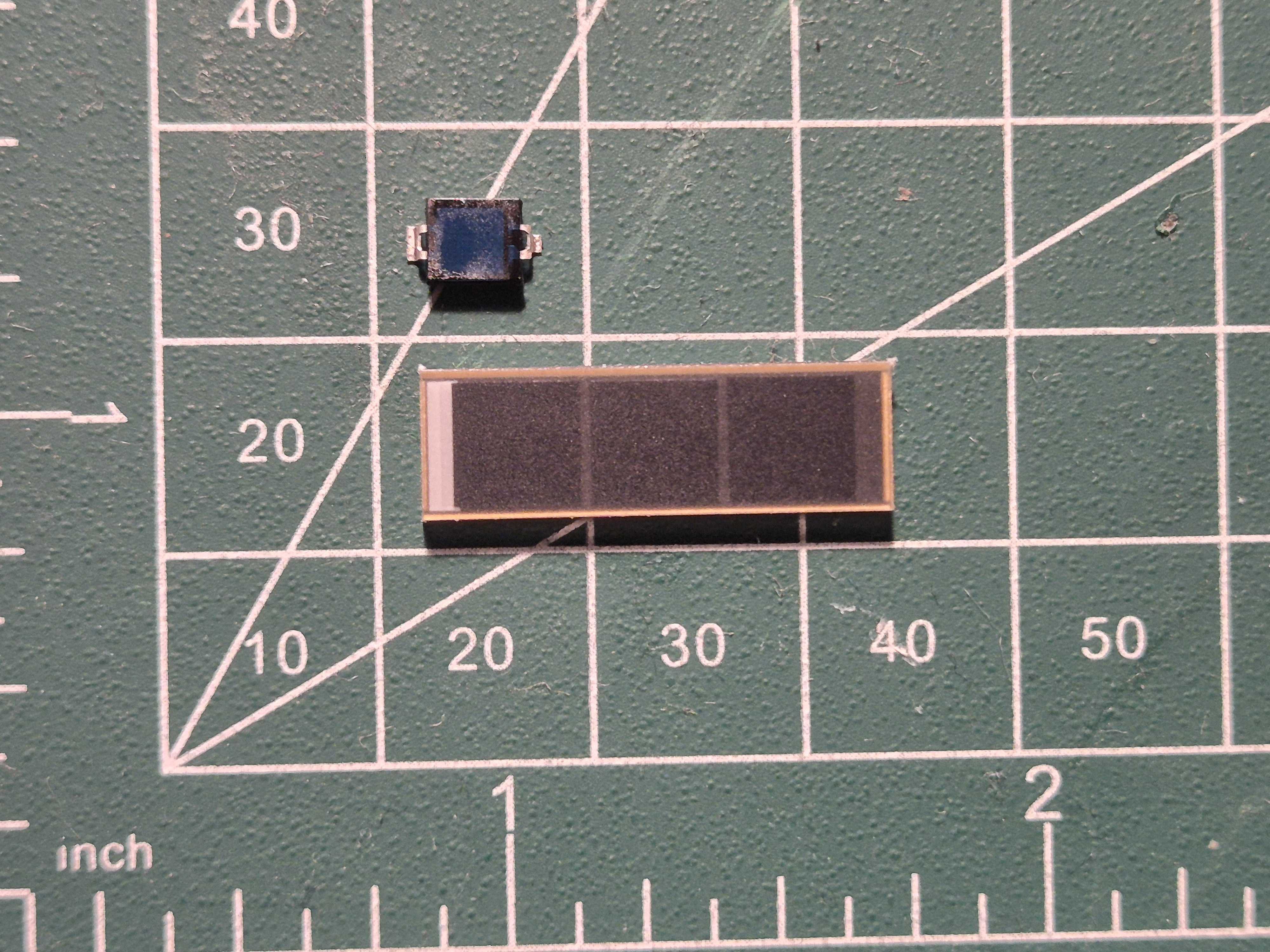
Here are the BP34W and KXOB25-03X4F-TB cells side by side.
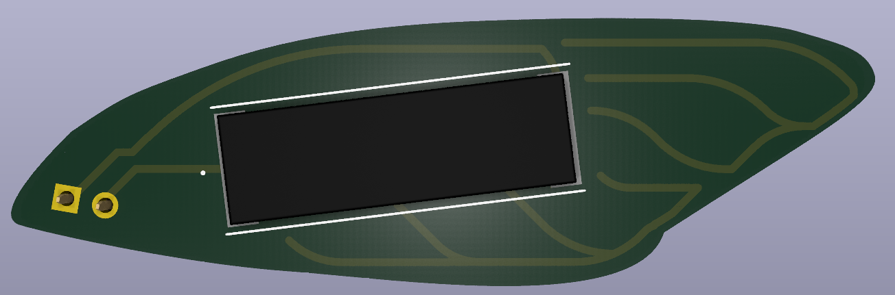
We used tracks in a combination of functional and aesthetic ways, playing with the inherent rigidity of pcb design and the organic shapes of the cicada's wings and veins.
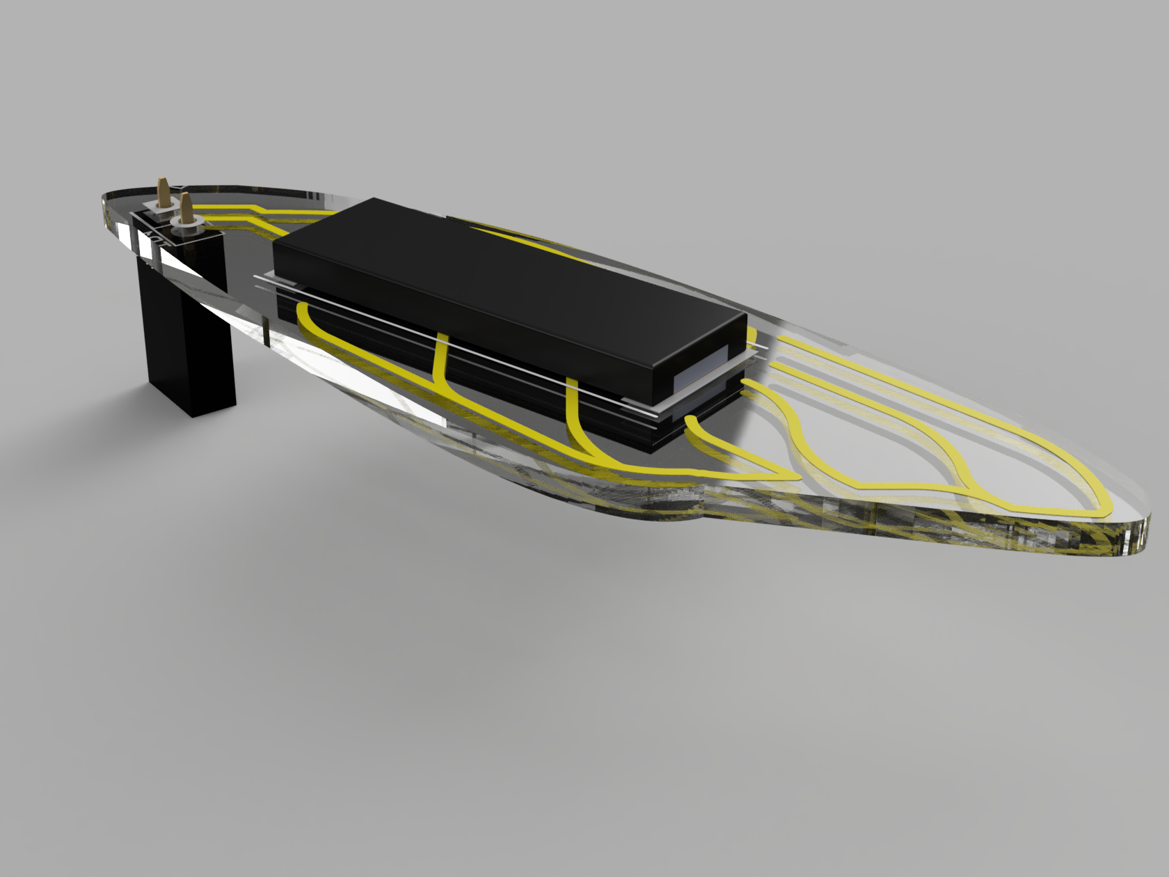
The original plan for the wings was to have them made from PCBway's new glass PCB material. We think 1mm thick glass would look great and also want to try out this new material.
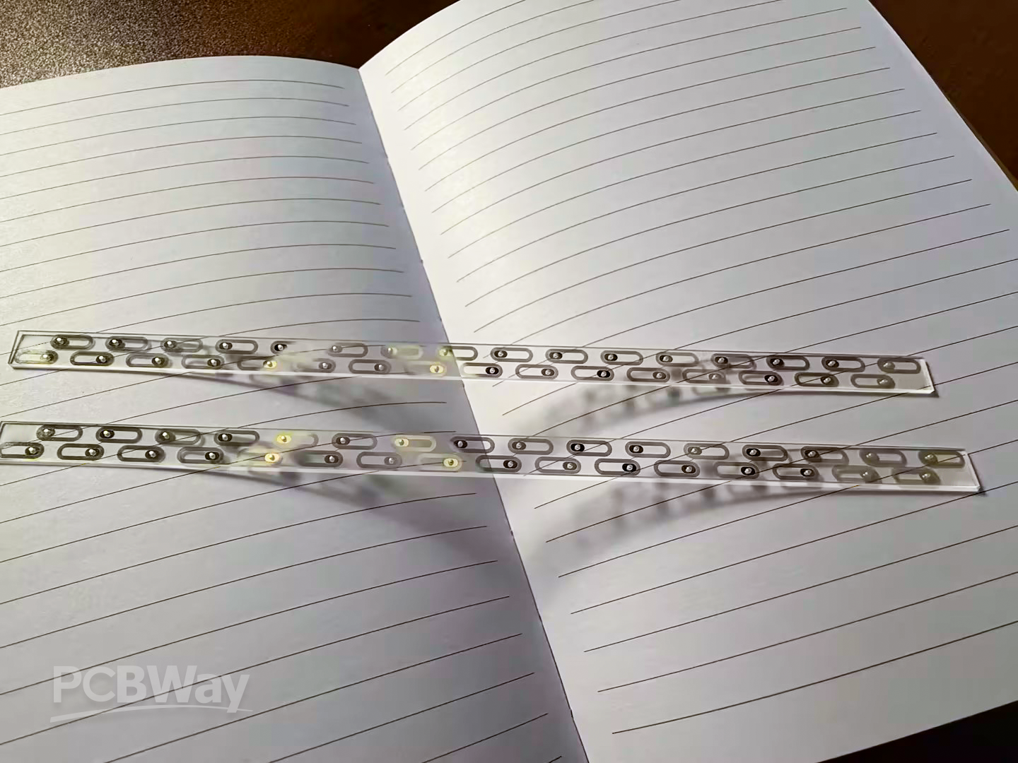
Since the process of getting glass PCBs isn't as straight forward as transparent FPC, we have decided to start with transparent FPC for now while we explore the glass PCB option with PCBWay.
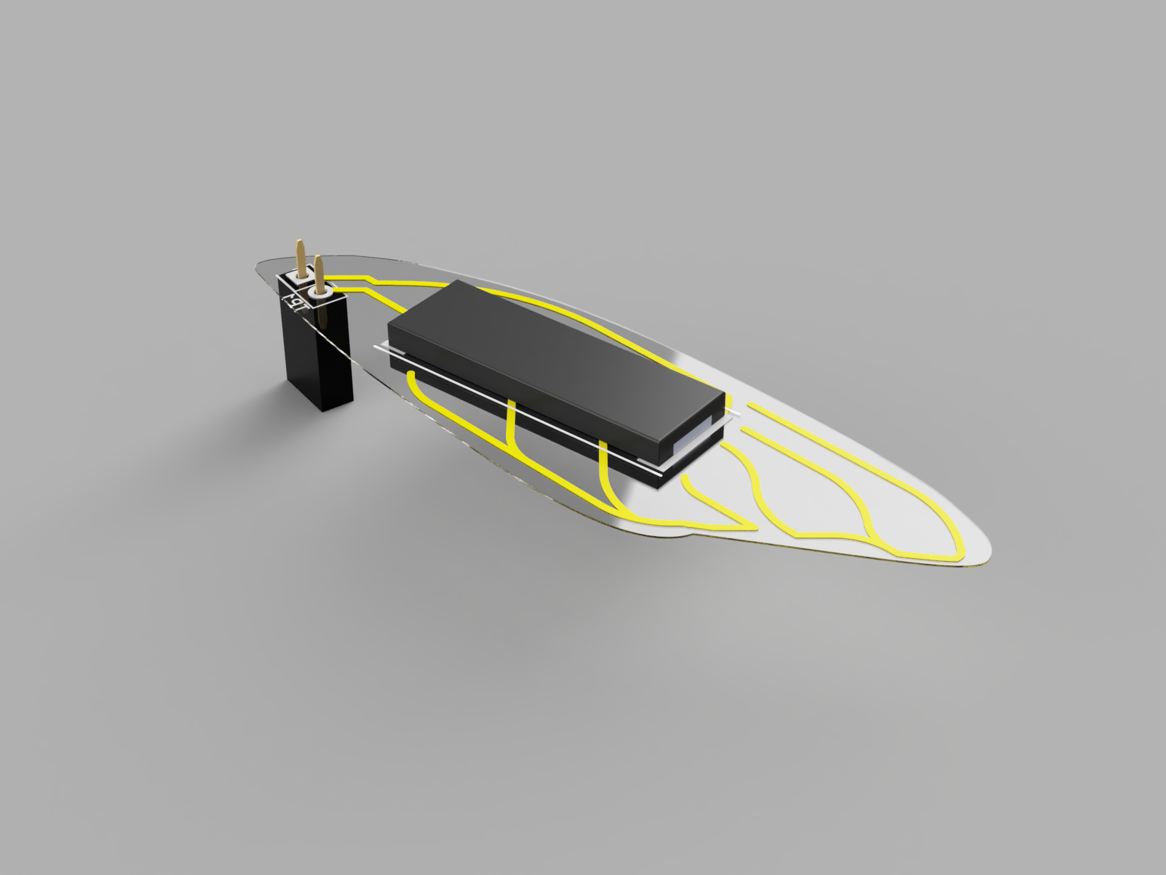
The problem with the FPC approach is the 0.24mm thickness of FPC which we plan to stiffen a bit with some clear acetate sheets.
The Cicada body
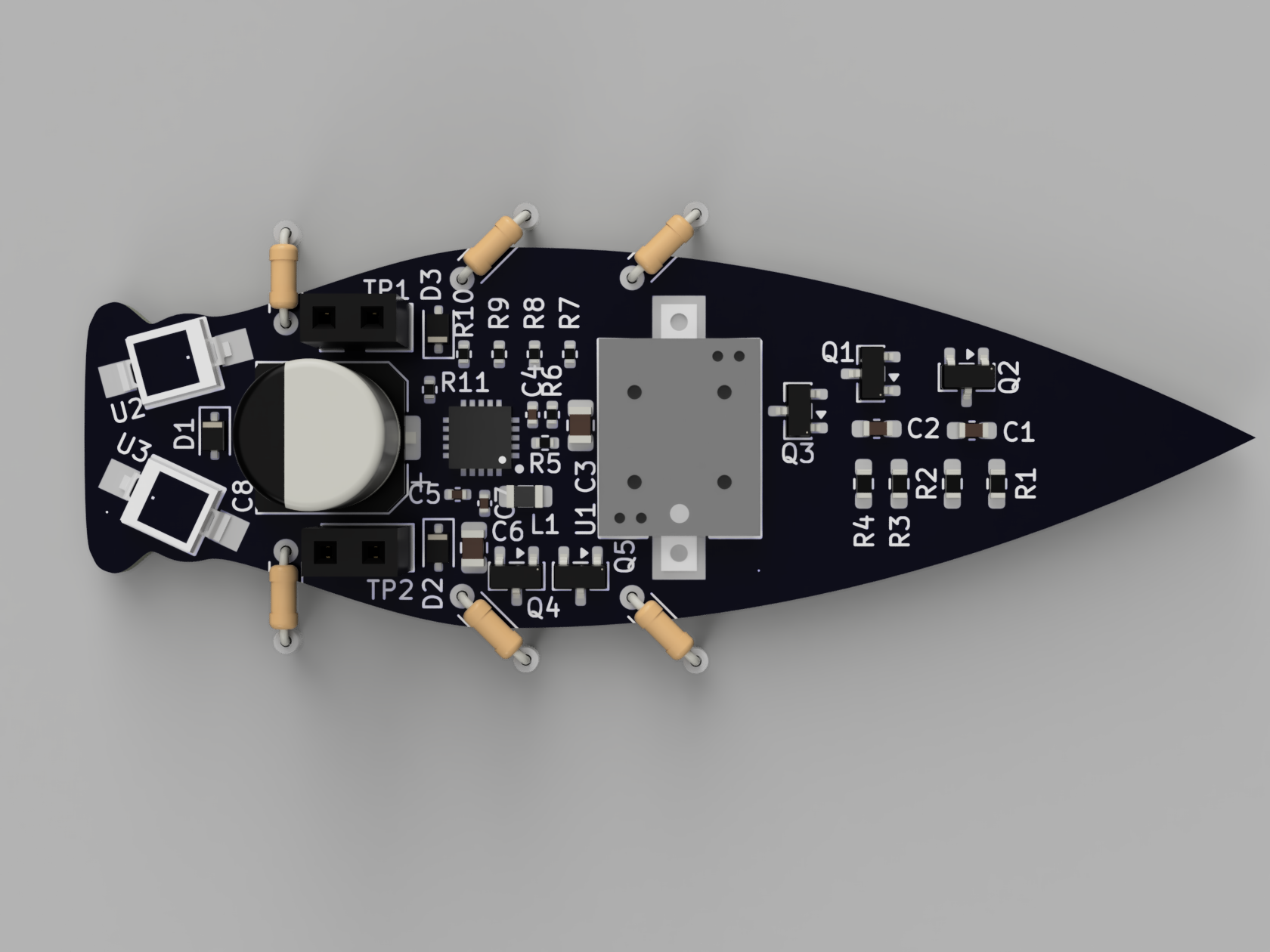
The git repo contains most of the gritty details along with a markdown detailing the calculations behind the system's operation, Fundamentally it consists of 2 solar inputs feeding into a BQ25505 energy harvester PMIC. This charges a 1mF capacitor to 3.6V. When charged, the VBAT_OK pin goes high and turns on power to the system.
The system that's powered consists of the above mentioned oscillator circuit connected to a N-Channel FET which drives a Piezo buzzer (GSC1102YB-3V4000) which is resonant at about 4kHz.
Expected behaviour
C≈ 1 mF (C8) if that is the dominant capacitance on the node that must reachVBAT_OK_HYST. (AnyCSTOR-class cap onVSTORadds in parallel on that node.)V_target≈ 3.6 V (from above), if you start near 0 V (cold start has extra phases; this is still a useful scale).I_net= average boost current into the tank minus leakage, divider current, and any sneaky paths — usually µA to low mA from a tiny panel, sotspans orders of magnitude.
Net average charge current I_net | Order of t to ~3.6 V on 1 mF |
|---|---|
| 0.5 mA | ~7 s |
| 3 mA | ~1.2 s |
| 10 mA | ~0.36 s |
So within about 10 seconds, we expect a chirp. But how long is that chirp?
Two different things:
- Tone frequency (oscillator sheet):
R2/R3≈ 174 kΩ,C1/C2= 1 nF ⇒ time constant τ ≈ 174 µs ⇒ astable period ~2 ln(2)·τ ≈ 0.24 ms ⇒ ~4 kHz, which matches a 4 kHz magnetic buzzer part. - Envelope length (how long
VBAT_OKstays high while the cap feeds the load): while the PFET is on, the storage node decays from ~VBAT_OK_HYSTto ~VBAT_OK_PROG, ΔV ≈ 1.2 V, so:
tchirp ≈ C⋅ΔV / ILoad
Using C ≈ 1 mF, ΔV ≈ 1.2 V:
So depending how hard we're driving the buzzer, that will shorten or lengthen the chirp. We may need to mod in some current limiting on buzzer to make it more noticable.
Average load current from +3V0 (osc + buzzer, order-of-magnitude) | ~Chirp length |
|---|---|
| 2 mA | ~0.6 s |
| 10 mA | ~0.12 s |
| 30 mA | ~40 ms |
Future steps
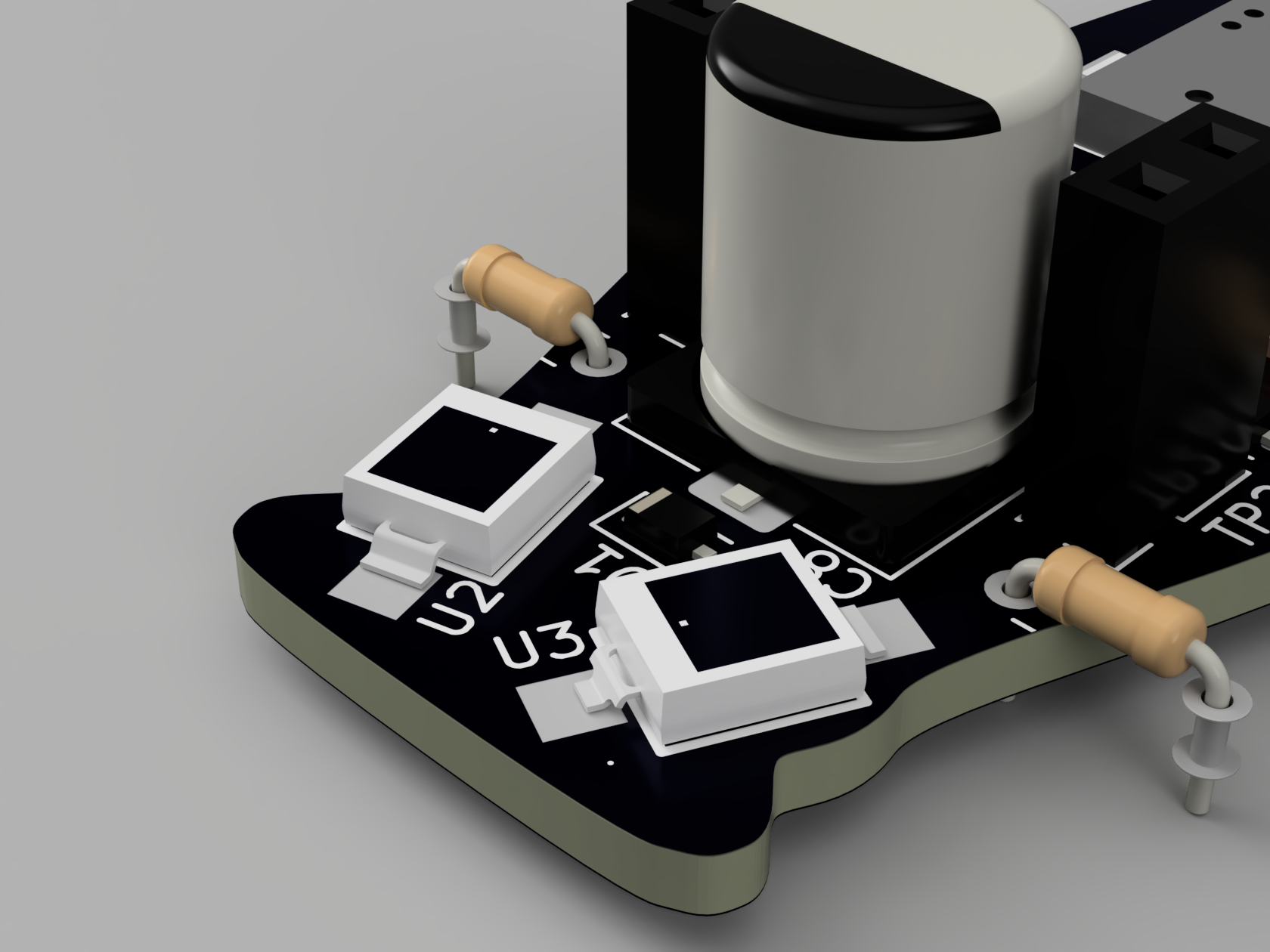
We've included some optional 'eyes' to the main cicada board. We've kept them unpopulated for now but will try running the system with only 2x BPW34. The charge time may be much longer on indoor light but it would allow for the wings to be clearer and make the aesthetics cooler.
We're working on trying to get sponsorship for the glass PCB as the cost involved in making them is rather high. We will update the project as this goes. We just think the glass look with the thicker 1mm glass would make for a interesting piece.
The initial PCBs should arrive soon from JLCPCB and we will write up some updates for its first power up.