 SnoWHandS
As soon as the PCBs arrived, I could resist but attempt to power it up!
Powering it from the bench, we got no smoke and a little current draw (large at first for that 1000uF cap).
But no sound . . . Great! Lets see whats going on here.
Investigating why no sound:
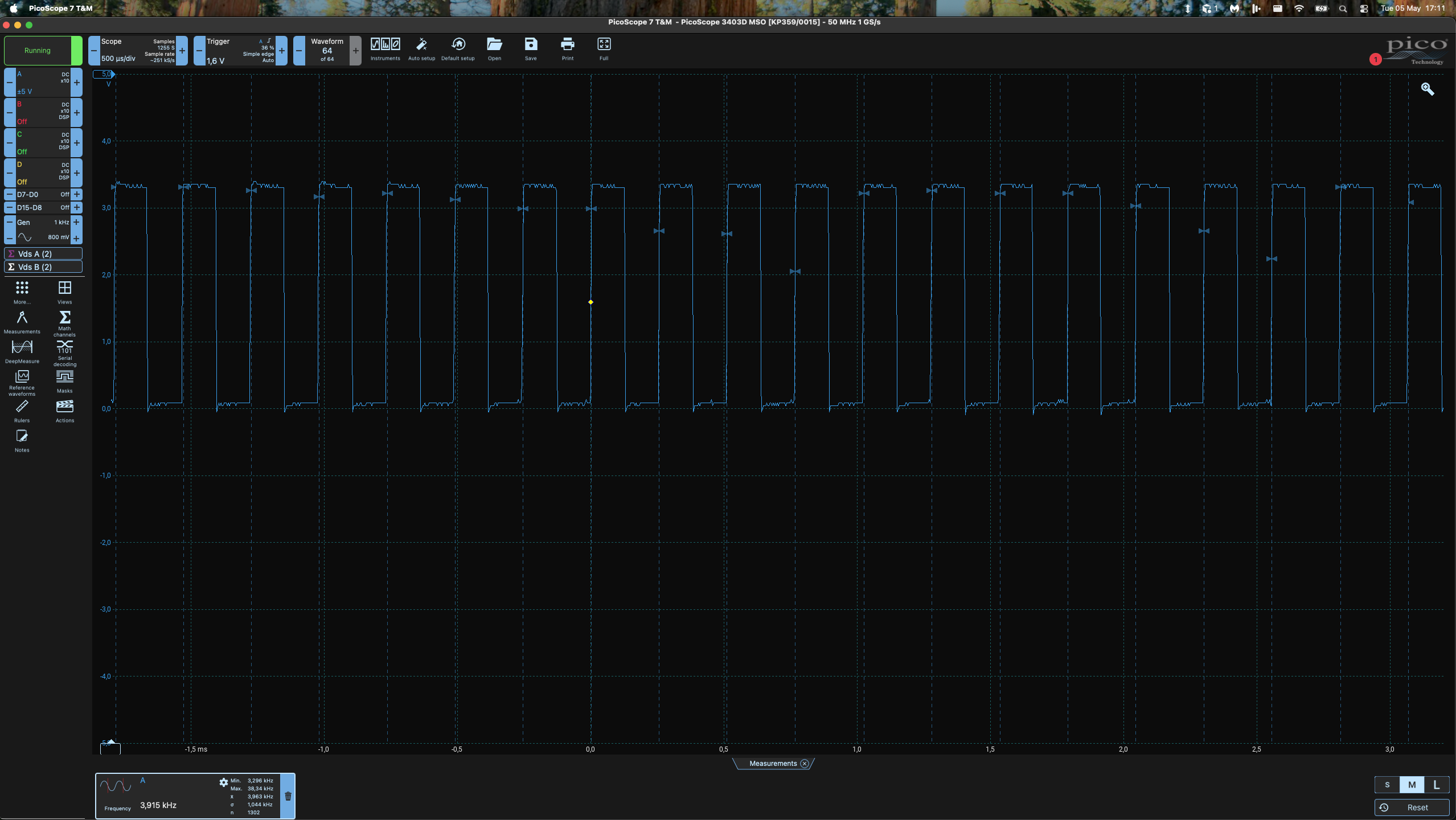
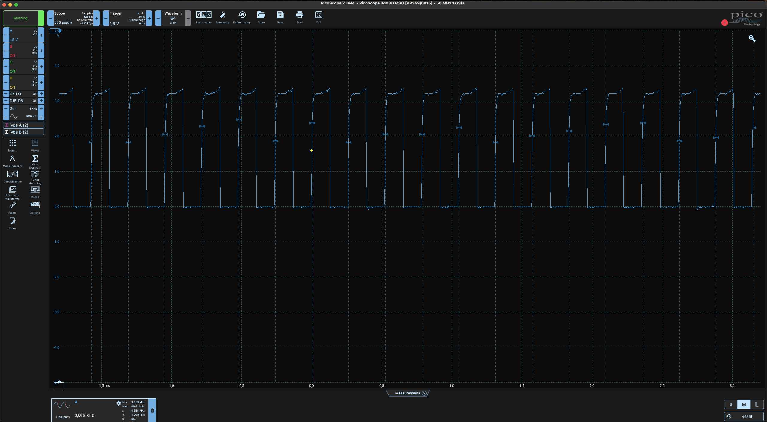
The first thing to check is our astable oscillator, so I checked the input to the gate of the piezo driving FET (Q3).
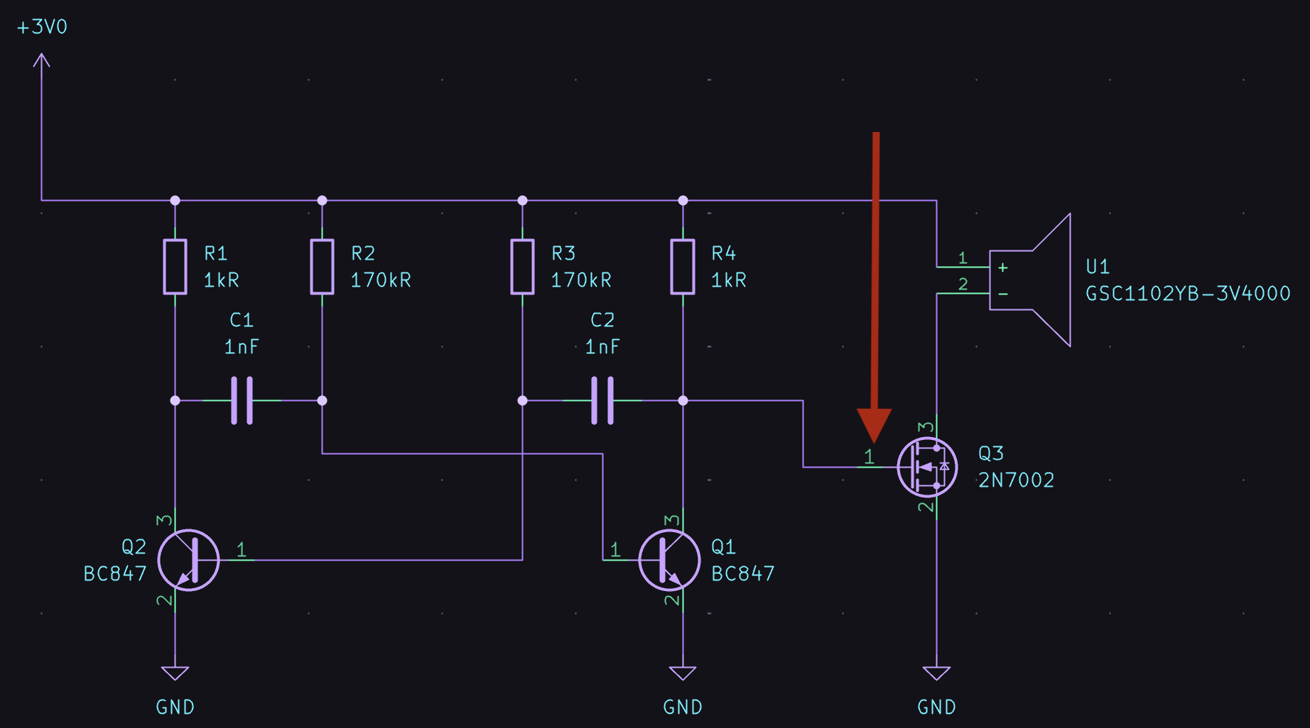
The output looked good and hit the mark we expected (3.3V @ ±3.915kHz):
Ok, great! So it must be something to do with the load / FET we are driving the load with.
Measuring the voltage on the drain of Q3 show us that the FET isn't turning on enough to pull the load to ground:
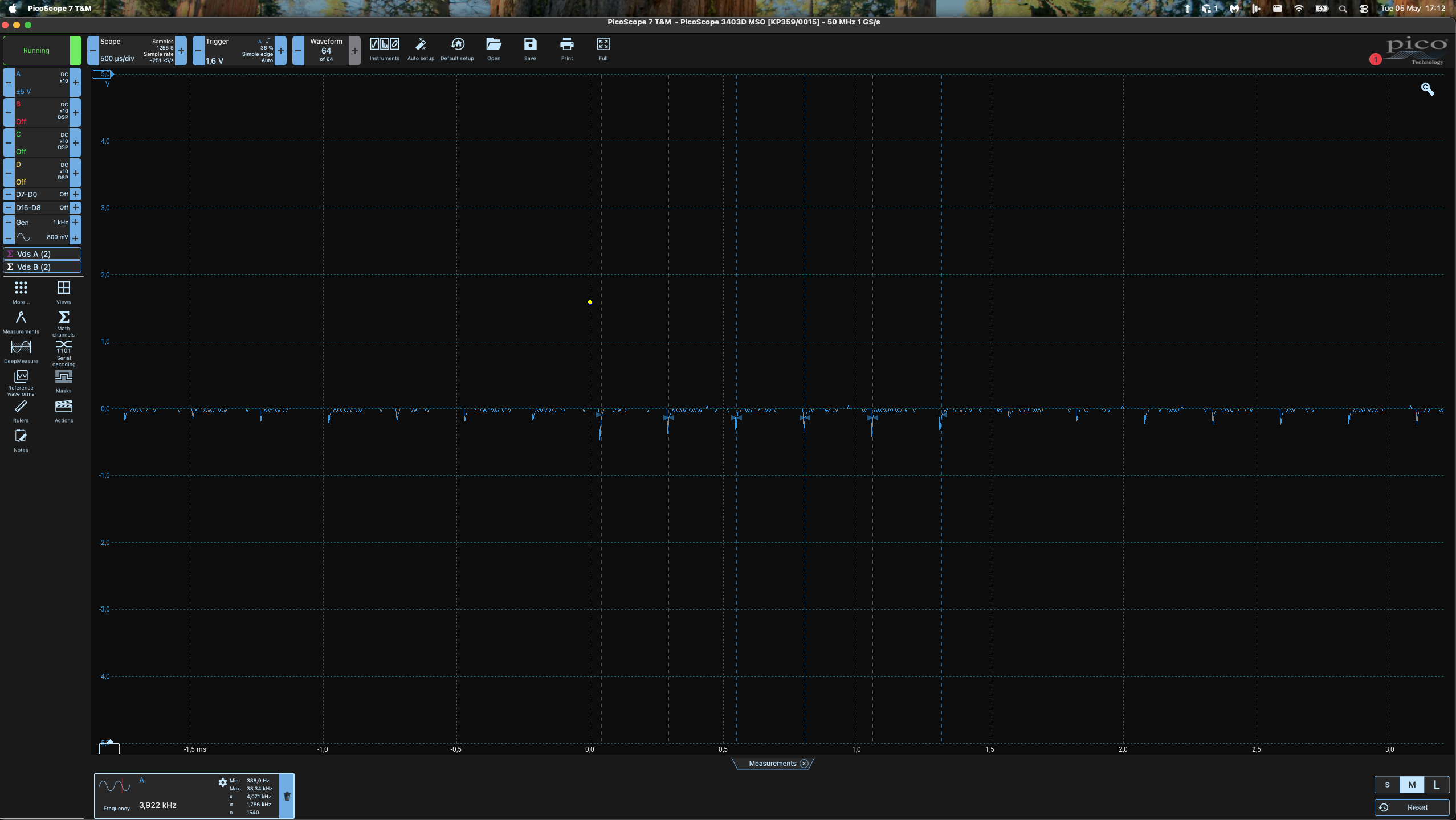
Strange, lets see what happens if we change the load and just check the Q3 FETs operation?
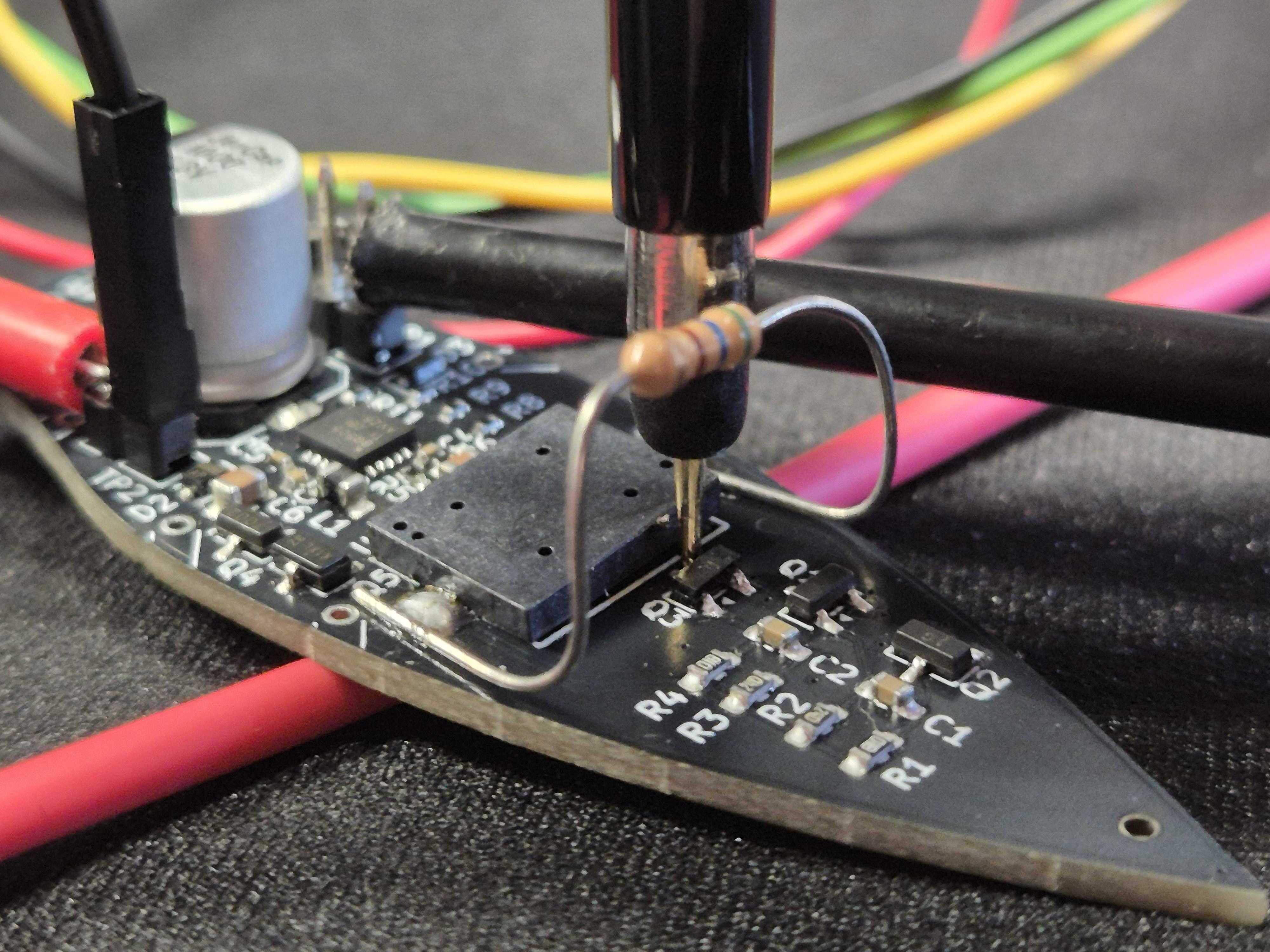
I disconnected the buzzer's positive leg and hooked up a 560Ω in series, Here's what's coming out of the FET (Q3):
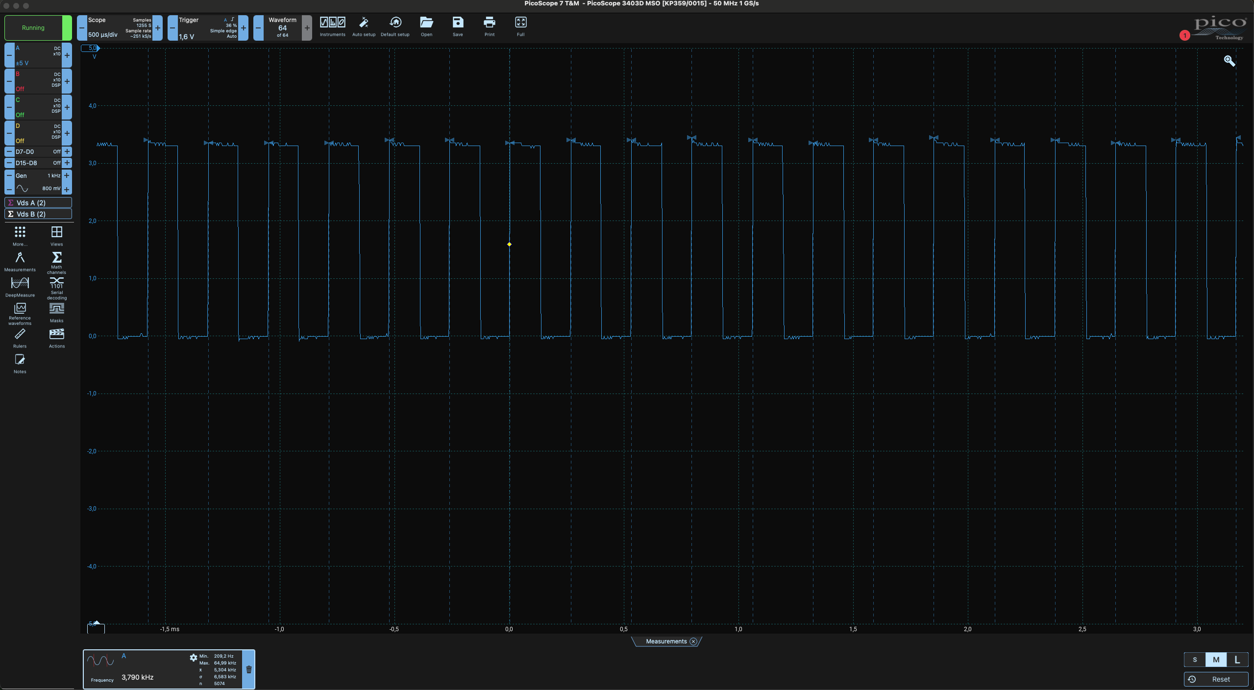
Alright so it seems we need some change in loading on the FET to get it working?
Turns out this might have to do with capacitive loading from the buzzer . . . What if? We make a bleeder circuit with this 560Ω in parallel with the buzzer?
The output seems to sing well as show here:
So this bleeder circuit is needed.
Why we need the 560Ω bleeder:
A passive piezo isn’t really “just a speaker.” It behaves like a capacitor with some mechanical stuff hanging off it. I’m driving it with a single N-channel MOSFET on the low side: buzzer “+” on 3.3 V, buzzer “−” on the drain, source on ground. When the FET is on, it’s great—it yanks that node hard to 0 V. When the FET is off, though, it isn’t magically tied to 3.3 V; it’s just not being pulled down anymore. For the node to move up toward the rail, charge has to flow to charge up all that capacitance.
Through the buzzer alone, that path is often weak or slow, so the low side never really makes it back up before the next edge. The voltage across the transducer stays small, so there’s almost nothing to make it move air. With a 560 Ω resistor across the buzzer, I gave that node a boring, predictable path from 3.3 V when the FET releases. The resistor isn’t there to “fix Vgs”—it’s there so the capacitive node can actually recover high.
When the FET turns on again, its on-resistance is tiny compared to 560 Ω, so it still wins and pulls the node low. I get something much closer to the square-ish wave a passive piezo wants, and the part becomes audible.
A future fix I’m eyeing: totem pole (half-bridge) drive
The bleeder works because it fakes a pull-up when my single N-FET lets go. The next step up—if I want a cleaner swing without bleeding so much DC through a resistor—is a totem pole: a high-side P-FET stacked above a low-side N-FET, with the piezo from the midpoint to ground. Idea: when the bottom device is on, the node slams low; when the top is on, the node is actively pulled high instead of crawling up through a bleeder.
For now, I'll experiment with different resistor values and perhaps mod in the totem pole idea on one!
Till the next update!
Discussions
Become a Hackaday.io Member
Create an account to leave a comment. Already have an account? Log In.